
System and Method of High-Resolution Digital Data Image Transmission

a digital data and image transmission technology, applied in the field of systems, can solve the problems of reducing the quality of video, requiring a large amount of bandwidth, and maintaining such a large bandwidth

Active Publication Date: 2013-02-28
AEROVIRONMENT INC
View PDF20 Cites 66 Cited by
  • Summary
  • Abstract
  • Description
  • Claims
  • Application Information

AI Technical Summary

Benefits of technology

The present invention relates to a system and method for transmitting still images and video feeds to a remote location. The system includes an aircraft with a digital video camera to capture still images and video frames. A video encoder converts the video frames into video packets, while a file server converts the still images into image data packets. A multiplexer combines the video and image data packets and sends them to the remote location. The system can also transmit data in different formats and allow for the separation of video and image data packets. The technical effects include improved data transmission efficiency and reduced data loss during transmission.

Problems solved by technology

Since video involves sending multiple still frame images from a camera each second, streaming video requires a great deal of bandwidth.
Maintaining such a large bandwidth is a challenge both for aircraft video systems that must process and stream the raw video data and ground stations that have limited bandwidth to receive the video feed.
One of the tradeoffs to address these concerns is that video quality is degraded by either lowering the resolution (e.g. number of pixels) and / or reducing the image frame rate in order to decrease the required bandwidth.
Thus, a video feed allows a remote operator to follow a target, but it does not provide a high resolution image of the target for detailed analysis.

Method used


Image

  • System and Method of High-Resolution Digital Data Image Transmission
  • System and Method of High-Resolution Digital Data Image Transmission
  • System and Method of High-Resolution Digital Data Image Transmission

Examples


Embodiment Construction

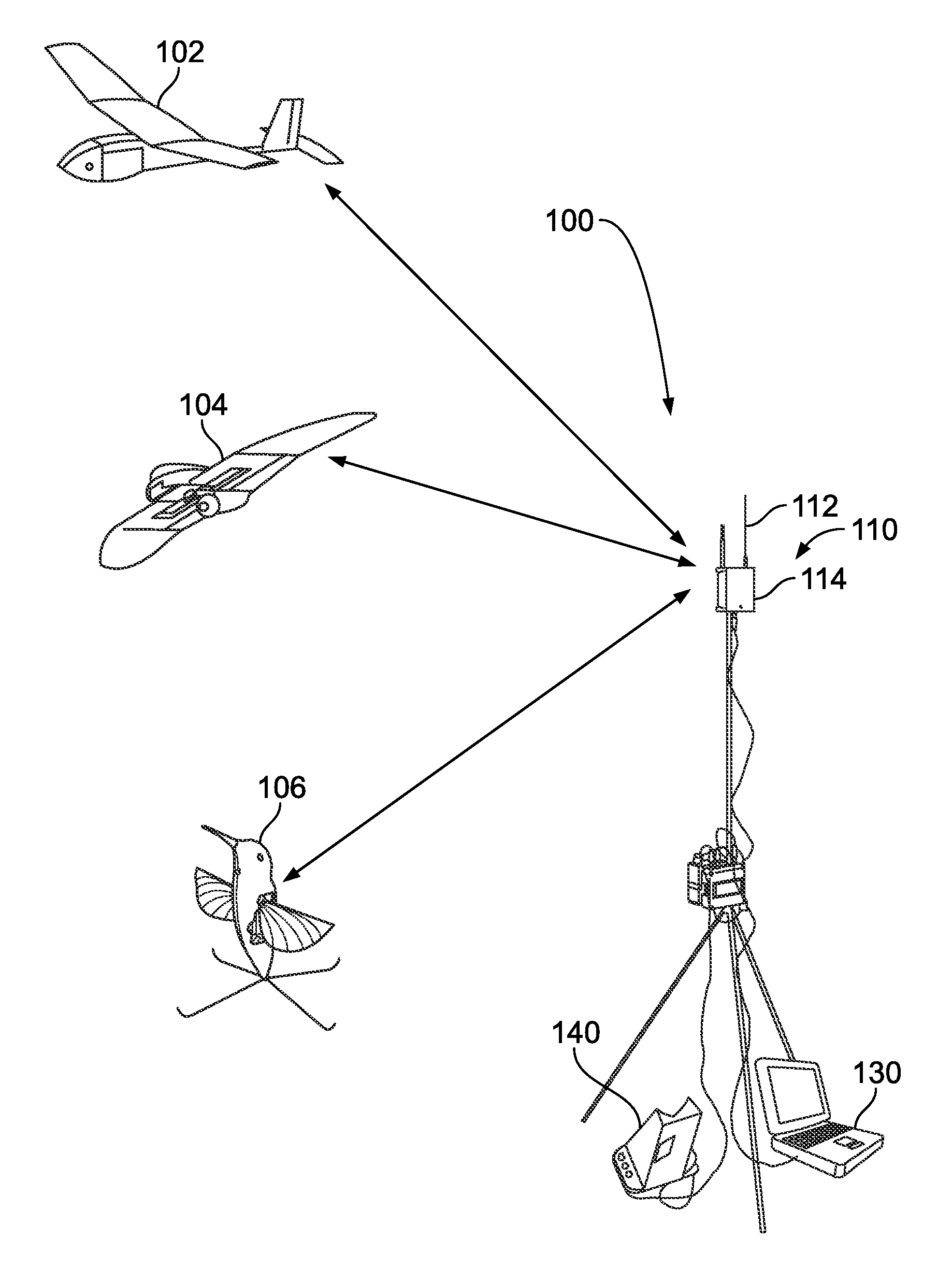
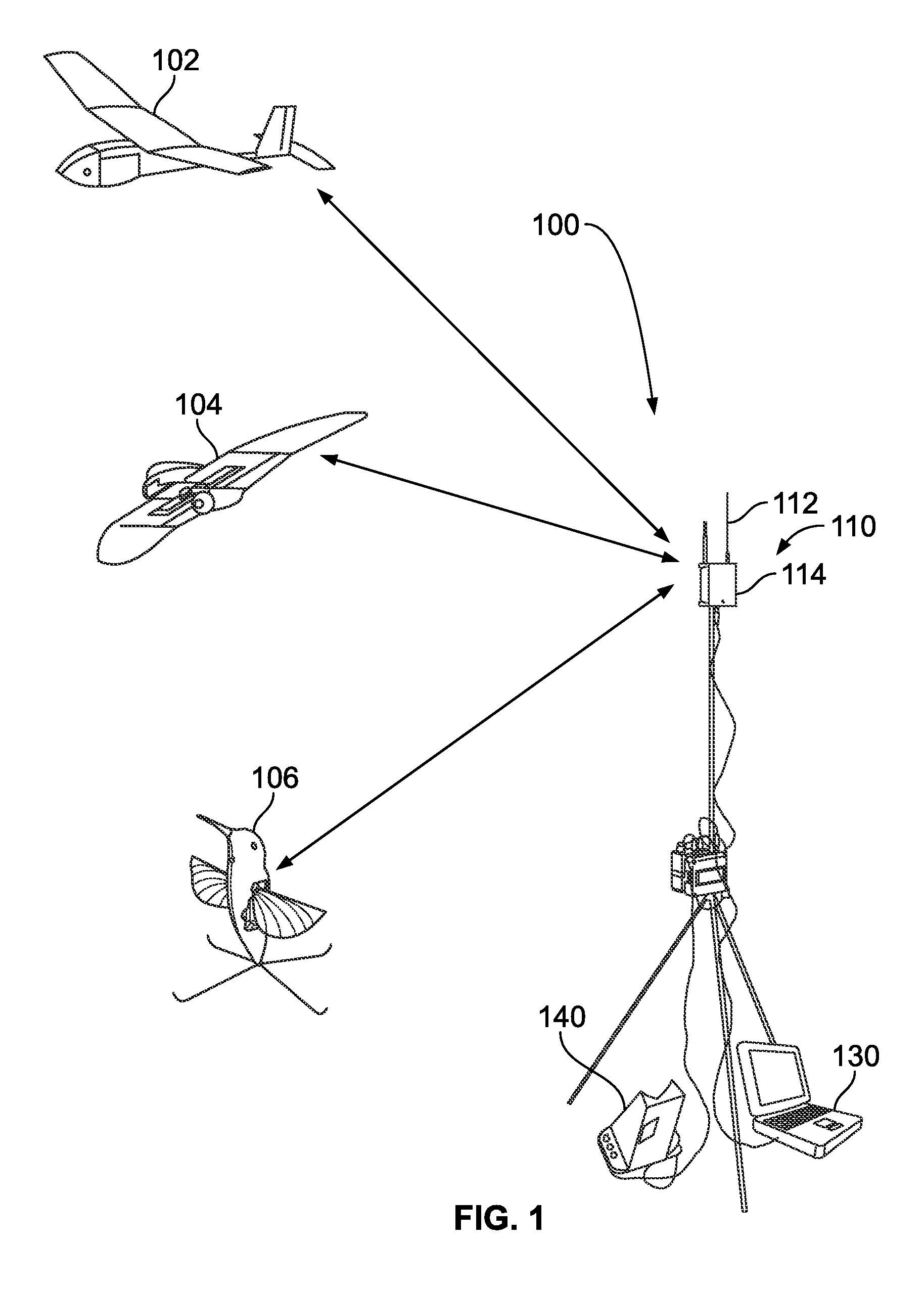
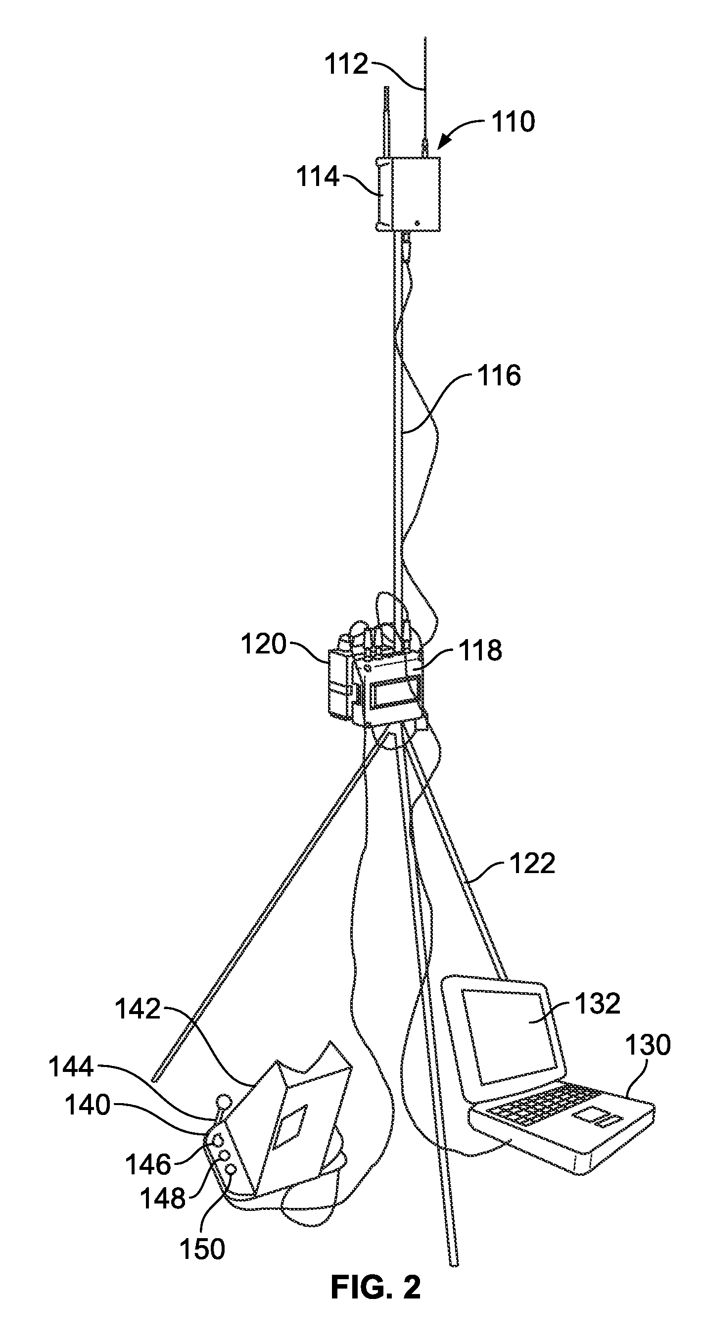
[0019]FIG. 1 is a diagram of an aerial surveillance system 100 including drone aircraft 102, 104, and 106 and a mobile ground control station 110. The ground control station 110 allocates bandwidth on a single channel to each of the aircraft 102, 104, and 106 for sending surveillance data to the ground control station 110. In this example, the ground control station 110 may manually control one of the aircraft 102, 104, or 106. The other aircraft 102, 104, and 106 may be programmed in an automatic flight mode to navigate to certain waypoints, hover, and or complete automated stored flight patterns that do not require human operator control.

[0020]Each of the aircraft 102, 104, and 106 in FIG. 1 include various systems including a structural control system and a flight control system. Both the structural control system and the flight control system receive data from numerous sources. One such source is a communications unit configured to receive instructions from a ground controller (...


PUM


Abstract

A system and method for transmitting still images and a video feed from an unmanned aerial vehicle to a ground station is disclosed. The system includes an aircraft including a digital video camera to capture still images and video frames of an object. A video encoder is coupled to the camera to provide a video output including video packets. A file server is coupled to the camera to provide a still image output including image data packets. A multiplexer is coupled to the video output and the still image output. The multiplexer produces a data transmission including the video packets and the image data packets. A transmitter sends the data transmission to the ground station. The ground station receives the data transmission and demultiplexes the packets into separate video and image data packets. The ground control station may select the ratio the video stream images in relation to the still image to be transmitted from the aircraft.

Description

TECHNICAL FIELD[0001]The present disclosure relates generally to transmission of both a still image and a video stream and, more particularly, to a system that allows the combination of transmission of a still image while maintaining a video stream from an aircraft to a ground station.BACKGROUND[0002]The way that the Vietnam War is now remembered as the helicopter war, the current conflicts in Iraq and Afghanistan may be remembered for the use of unmanned drones or unmanned aerial vehicles (UAVs). Drones may facilitate remote intelligence gathering, alleviating the need for foot soldiers to enter into hostile areas “blind,” with little or no information about the location and strength of hostile forces. Drones may provide close combat support, such as identifying and eliminating targets of interest, alleviating the need to expose soldiers and / or airmen to potential small arms fire, mortars, rocket grenades, road-side bombs, anti-aircraft weaponry, missiles, and other dangers.[0003]I...

Claims


Application Information

Patent Timeline
IPC IPC(8): H04N7/18
CPCH04N21/23614H04N5/232H04N7/185H04N21/8153H04N21/2743H04N21/41422H04N21/2187H04B7/18504H04N23/661H04N23/60H04N21/23611H04N21/4223H04N21/4348
Inventor OMER, THOMASSZAREK, THOMASMCBRIDE, JEFFERSON C.
Owner AEROVIRONMENT INC
Learn More