Backlight unit and manufacturing method thereof, and liquid crystal display device having the same

a backlight unit and liquid crystal display technology, applied in the direction of instruments, lighting and heating apparatus, optical elements, etc., can solve the problems of productivity decline, inconvenient use of optical resin layers, etc., and achieve the effect of excellent color reproduction

Active Publication Date: 2013-02-28
SAMSUNG ELECTRONICS CO LTD
View PDF5 Cites 79 Cited by
  • Summary
  • Abstract
  • Description
  • Claims
  • Application Information

AI Technical Summary

Benefits of technology

[0011]Accordingly, one or more exemplary embodiments provide a backlight unit which is excellent in color reproduction, and an LCD device having the same.
[0013]Still another exemplary embodiment is to provide a backlight unit to which a QD bar can be easily fastened, and a manufacturing method thereof.
[0014]Yet another exemplary embodiment is to provide a backlight unit having a structure for improving workability and increasing productivity, and a manufacturing method thereof.
[0015]Still another exemplary embodiment is to provide a backlight unit having a structure in which light emitted by an LED is transferred to a light guide plate without distortion, and an LCD device having the same.

Problems solved by technology

Also, the color reproduction, efficiency and white coordinate of a panel is susceptible to matching between a peak wavelength of three colors, red, green and blue (R, G, B), of the white LED and a peak wavelength of a color filter for the liquid crystal of the LCD device.
However, it is very inconvenient to use the optical resin layer or the adhesive layer 40, 50 in the adhesion for the QD bar 30, and thus productivity decreases.
Further, the optical resin layer or the adhesive may distort the light emitted from the LED and the QD bar.

Method used


Image

  • Backlight unit and manufacturing method thereof, and liquid crystal display device having the same
  • Backlight unit and manufacturing method thereof, and liquid crystal display device having the same
  • Backlight unit and manufacturing method thereof, and liquid crystal display device having the same

Examples


Embodiment Construction

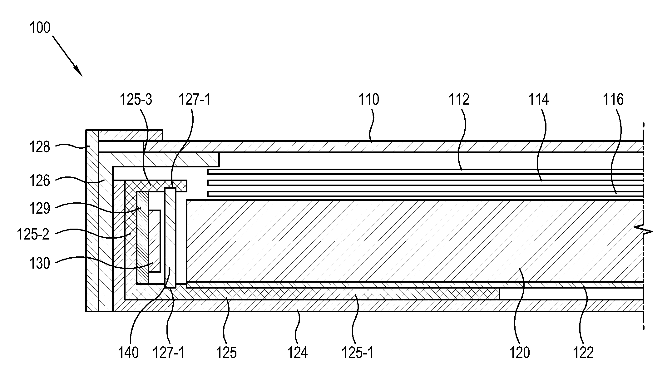
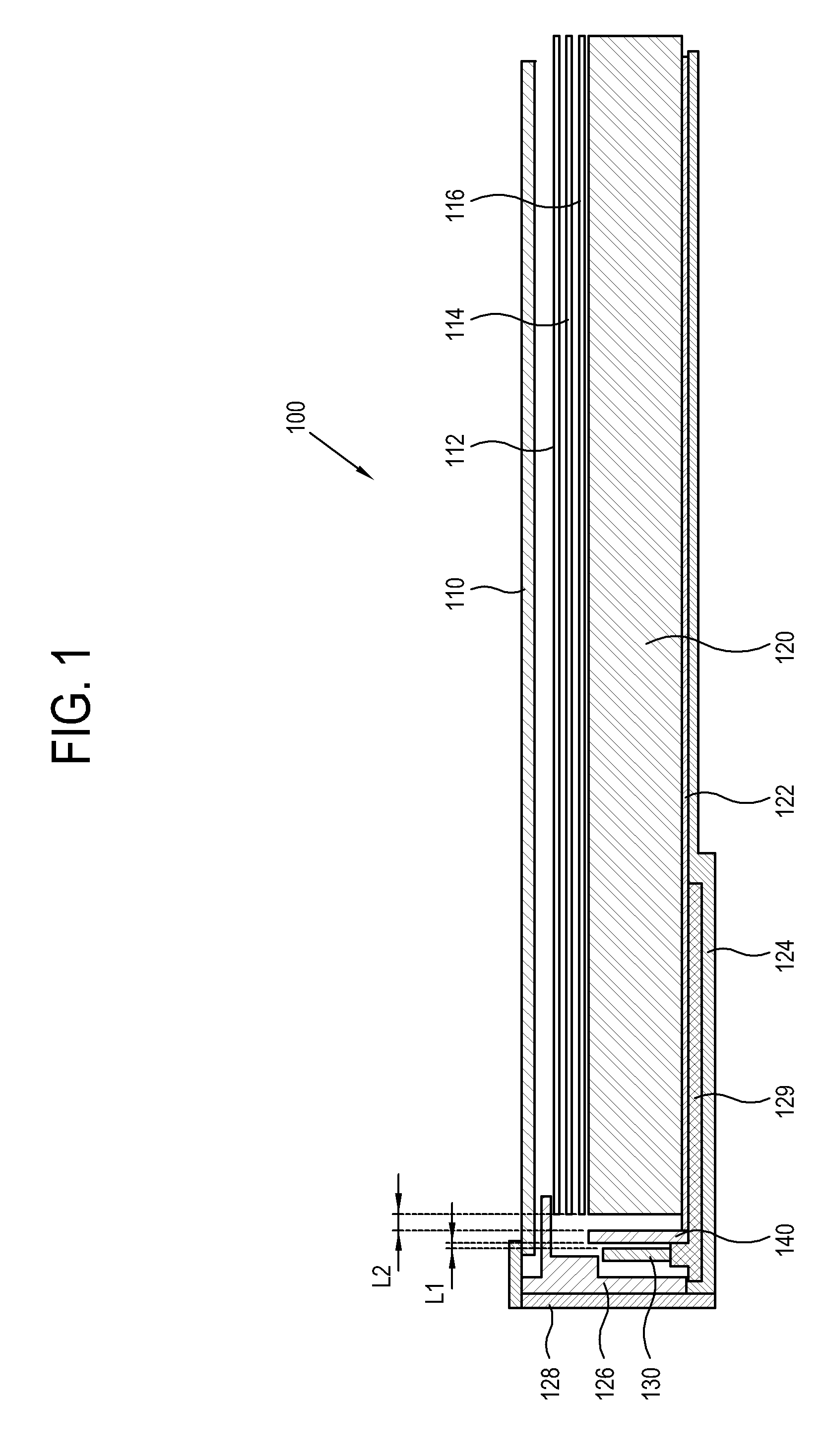
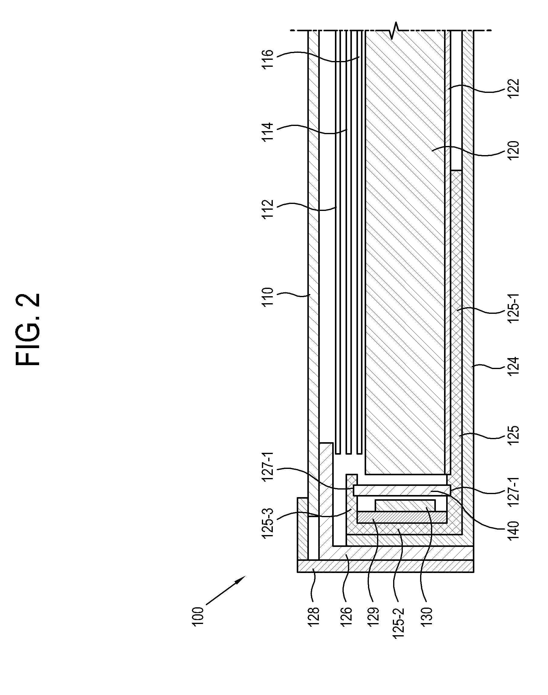
[0062]Below, exemplary embodiments will be described in detail with reference to accompanying drawings. For the convenience of description, elements having no direct relationship to the exemplary embodiments are omitted for clarity, and like reference numerals refer to like elements throughout. Here, the “rear” refers to a direction where a light guide plate 120 is placed in an LCD panel 110, and the “up,”“down,”“left” and “right” are defined with respect to the front of the LCD panel 110.

[0063]As shown in FIG. 1, an LCD device 100 includes an LCD panel 110 and a backlight unit. The backlight unit includes a dual brightness enhance film (DBEF) sheet 112, a prism sheet 114, a diffuser sheet 116, a light guide plate 120, a reflection sheet 122, an LED 130 and a QD bar 140 arranged in sequence on the rear of the LCD panel 110.

[0064]In the LCD panel 110, a nematic liquid crystal is interposed between two sheets of glass, and counter electrodes with a thin film transistor are arranged on...


PUM

PropertyMeasurementUnit
coloraaaaaaaaaa
elastic projectionaaaaaaaaaa
color reproductionaaaaaaaaaa

Abstract

A backlight unit is provided which includes: a light guide plate which guides incident light from a lateral side of the light guide plate toward a liquid crystal display (LCD) panel placed in front of the light guide plate; a light source unit which includes a light source which emits the light and a light source supporting member which supports the light source and is arranged adjacent to the lateral side of the light guide plate; a supporting frame which is arranged in the backlight unit; a quantum dot (QD) bar which is arranged between the lateral side of the light guide plate and the light source and changes a color of the light emitted from the light source; and a QD-bar fastening unit which fastens the QD bar to at least one of the light source supporting member and the supporting frame.

Description

CROSS-REFERENCE TO RELATED APPLICATION[0001]This application claims priority from Korean Patent Application No. 10-2011-0085525, filed on Aug. 26, 2011 in the Korean Intellectual Property Office, the disclosure of which is incorporated herein by reference.BACKGROUND[0002]1. Field[0003]Apparatuses and methods consistent with the exemplary embodiments relate to a liquid crystal display (LCD) device, and more particularly, to a backlight unit employing a quantum dot (QD) bar and a light emitting diode (LED) as a light source, a manufacturing method thereof, and an LCD device having the same.[0004]2. Description of the Related Art[0005]A backlight unit for an LCD device includes light emitting diodes 10 arranged along a lateral side of a light guide plate 20 as shown in FIG. 18. Light emitted from the LED 10 enters the lateral sides of the light guide plate 20, propagates to the center of the light guide plate 20 by total reflection, and exits the light guide plate 20 through a front pa...

Claims


Application Information

Patent Timeline
Patent Type & Authority Applications(United States)
IPC IPC(8): G02F1/13357F21V17/00G09F13/18
CPCG02F1/133603G02F1/133615G02F2001/133317Y10T29/49002G02B6/0073G02B6/0085G02B6/009G02F2001/133614G02F1/133317G02F1/133614G02F1/1333G02F1/1335
Inventor HUR, GIL-TAECHOI, HYEONG-SIKCHO, KUN-HOSEO, JEONG-PHILKWON, YONG-HUNLEE, KYE-HOONCHOI, SUK-JULEE, YOUNG-MIN
Owner SAMSUNG ELECTRONICS CO LTD
Why Eureka
Try Eureka