Athermal apochromatic telecentric f-theta lens with low f-number
a technology of apochromatic telecentric and lens, applied in the field of optical lenses, can solve the problems of 362 lenses that are not suitable for surveillance and reconnaissance applications, cannot be used in applications requiring a wide spectrum, and are only suitable for laser systems applications, so as to minimize the amount of light lost and light incident
- Summary
- Abstract
- Description
- Claims
- Application Information
AI Technical Summary
Benefits of technology
Problems solved by technology
Method used
Image

Examples
first embodiment
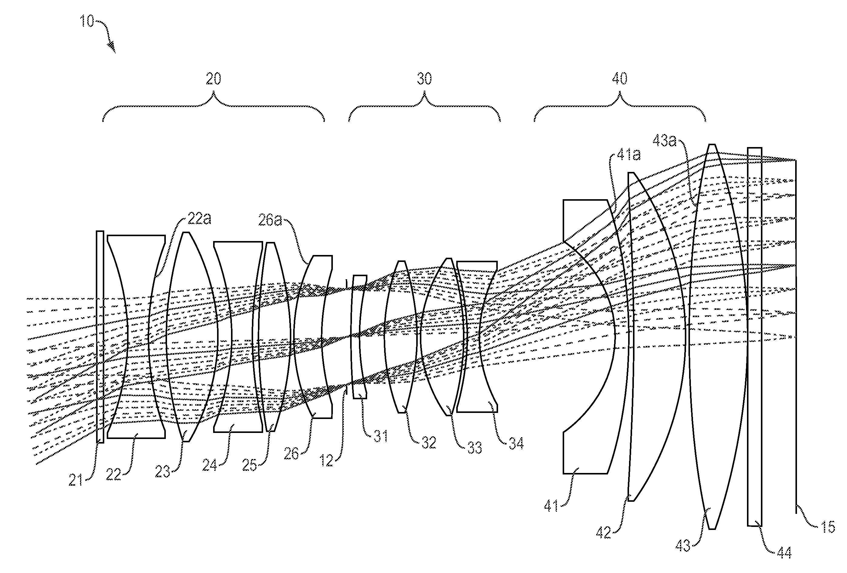
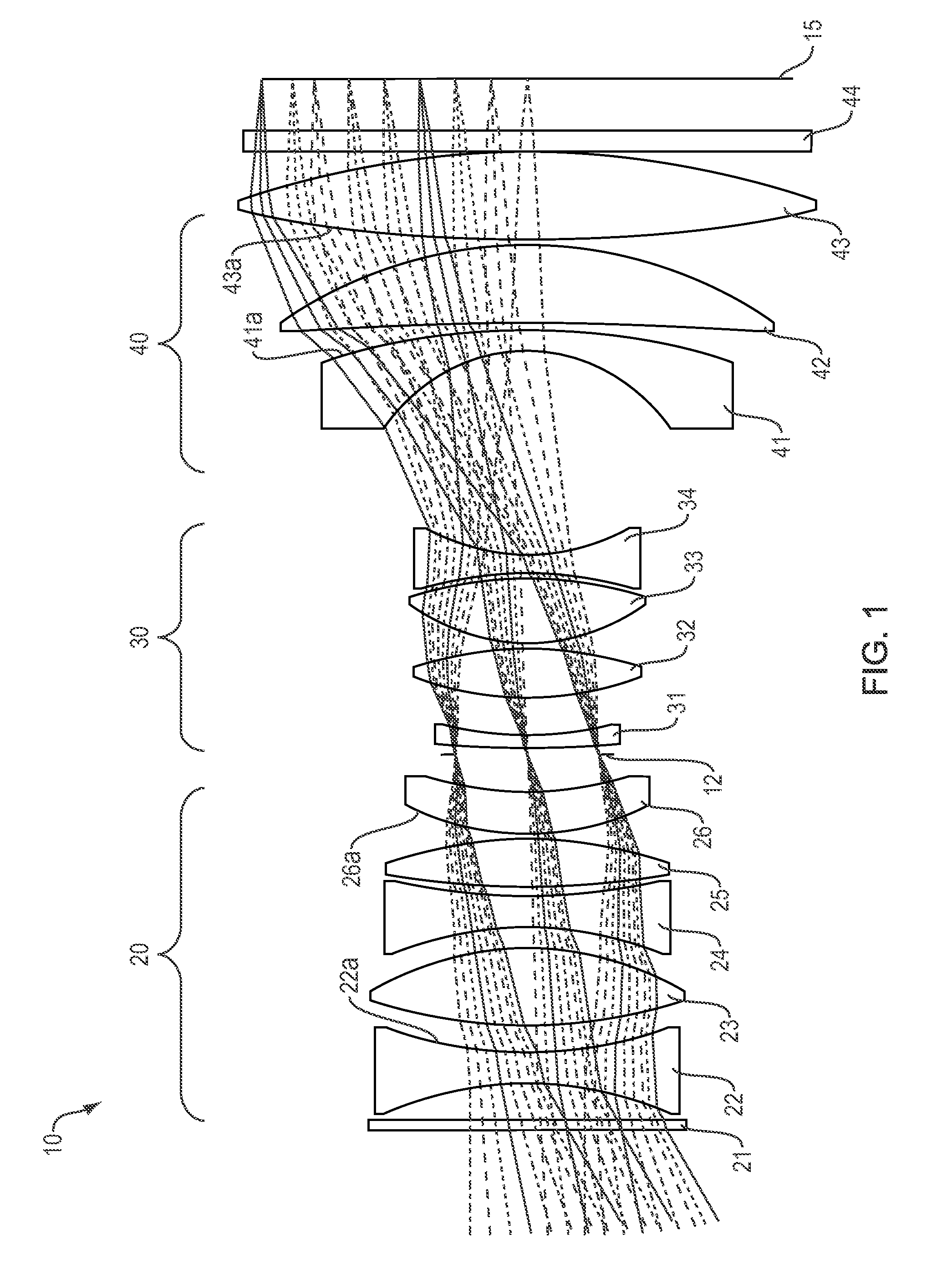
[0101]FIG. 1 is a cross section of the F-theta athermal lens 10 of the present invention. The lens includes a front window 21, a first optical group 20, a second optical group 30, a third optical group 40, and a back window 44 in order from the object to the image plane. An aperture stop 12 is located between the first and the second optical groups. An image of a target is formed on a focal plane array 60. In embodiments, the focal plane array incorporates CMOS with micro lenses, 2×2 Bayer filter geometry, and 1.8 Giga pixels. In other embodiments the image surface 60 incorporates CCD or a direct viewing screen.
[0102]The first optical group 20 has an overall positive optical power and is configured to receive light from the remote object and to direct the converged light onto the second optical group 30. The first optical group 20 includes five optical elements 22, 23, 24, 25 and 26, having, in order from the object to the image plane, a negative optical power, a positive optical po...
second embodiment
[0112]FIG. 8 is a cross sectional illustration of the F-theta athermal lens 100 of the present invention. The lens includes a front window 210, a first optical group 200, a second optical group 300, a third optical group 400 and a back window 440 in order from the object to the image plane 150. The aperture stop 110 is located between the first 200 and the third optical groups. An image of the target is formed on a focal plane array 150. In embodiments, the focal plane array 150 incorporates CMOS with micro lenses, 2×2 Bayer filter geometry, and 1.8 Giga pixels. In other embodiments, the image surface 150 may include CCD elements or a direct viewing screen.
[0113]In the embodiment of FIG. 8, the first optical group 200 has an overall negative optical power and is configured to receive light from a remote object and to direct the diverged light onto the second optical group 300. The first optical group 200 includes five optical elements 220, 230, 240, 250 and 260, having, in order fro...
third embodiment
[0121]FIG. 15 is a cross-sectional illustration of the F-theta athermal lens 1000 of the present invention. The lens 1000 includes a front window 2100, a first optical group 2000, a second optical group 3000, a third optical group 4000 and a back window 4400 in the stated order from the object to the image plane. The aperture stop 1100 is located between the first 2000 and second 3000 optical groups. An image of a remote object is formed on a focal plane array 1500. In embodiments, the focal plane array 1500 incorporates CMOS with micro lenses, 2×2 Bayer filter geometry, and 1.8 Giga pixels. In other embodiments, the image surface 1500 may incorporate CCD devices or a direct viewing screen.
[0122]The first optical group 2000 has an overall negative optical power and is configured to receive light from the remote object and to direct the diverged light onto the second optical group 3000. The first optical group 2000 includes three optical elements 2200, 2300 and 2400, having, in order...
PUM
 Abstract
Description
Claims
Application Information
 - R&D
- Intellectual Property
- Life Sciences
- Materials
- Tech Scout
- Unparalleled Data Quality
- Higher Quality Content
- 60% Fewer Hallucinations
Browse by: Latest US Patents, China's latest patents, Technical Efficacy Thesaurus, Application Domain, Technology Topic, Popular Technical Reports.
© 2025 PatSnap. All rights reserved.Legal|Privacy policy|Modern Slavery Act Transparency Statement|Sitemap|About US| Contact US: help@patsnap.com