Low distortion athermalized imaging lens

a low-distortion, imaging lens technology, applied in the field of optics, can solve the problems of not being corrected, affecting the accuracy of remote aerial high-resolution photography and precise mapping, significant field curvature and secondary spectrum, etc., to minimize both the amount of light lost and the amount of light incident.

Active Publication Date: 2013-02-28
BAE SYST INFORMATION & ELECTRONICS SYST INTERGRATION INC
View PDF1 Cites 21 Cited by
  • Summary
  • Abstract
  • Description
  • Claims
  • Application Information

AI Technical Summary

Benefits of technology

[0053]Embodiments have a focal plane diameter of 104 mm and are compatible for use with a CMOS 1.8 gigapixel multiple FPA (focal plane array) having a 2×2 Bayer filter geometry and a pixel size of 2.2 μm×2.2 μm, wherein each CMOS image sensor pixel includes a series of dielectric layers above the photo detector, with a micro lens on top of each pixel to focus light onto the active area of the pixel floor, thereby minimizing both the amount of light lost and the amount of light incident on adjacent photodiodes. In various embodiments, secondary color is corrected so as to take full advantage of a high resolution FPA.
[0058]In various embodiments, the lens has a focal plane of at least 104 mm. In some of these embodiments the lens is compatible for use with a CMOS 1.8 gigapixel multiple FPA (focal plane array) having a 2×2 Bayer filter geometry and a pixel size of 2.2 μm×2.2 μm, wherein each CMOS image sensor pixel includes a series of dielectric layers above the photo detector, with a micro lens on top of each pixel to focus light onto the active area of the pixel floor, thereby minimizing both the amount of light lost and the amount of light incident on adjacent photodiodes.

Problems solved by technology

At least for these reasons, the '714 lens is not useable for remote aerial high resolution photography and precise mapping.
However, the '520 lens is not corrected for distortion, and has a significant field curvature and secondary spectrum.
However, distortion and secondary spectrum are not corrected.
The '078 lens is rather complicated, has a large overall length and a small field of view.
However, this approach is highly undesirable, because additional electronics and software are needed to perform and monitor the necessary adjustments.

Method used


Image

  • Low distortion athermalized imaging lens
  • Low distortion athermalized imaging lens
  • Low distortion athermalized imaging lens

Examples


first embodiment

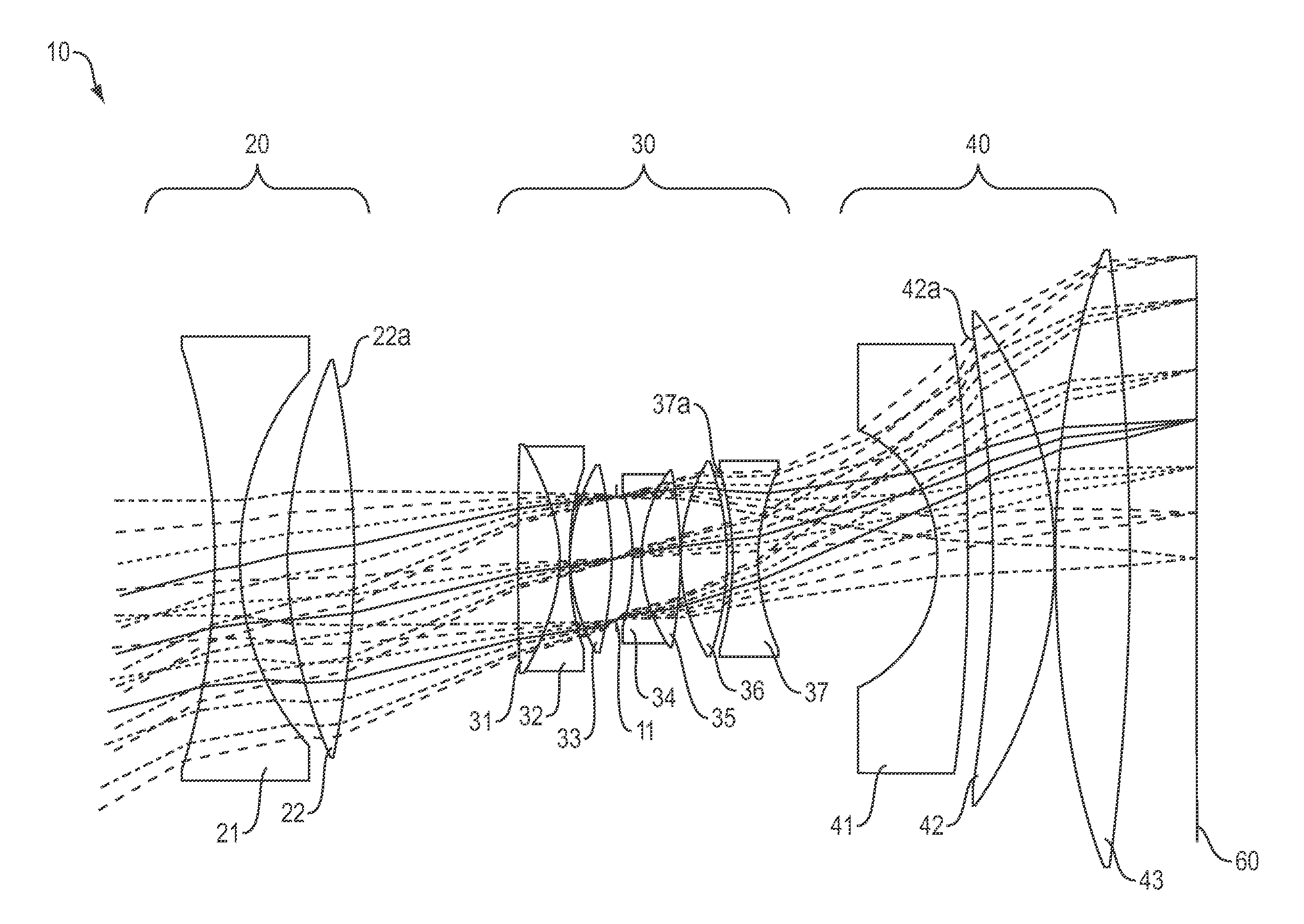
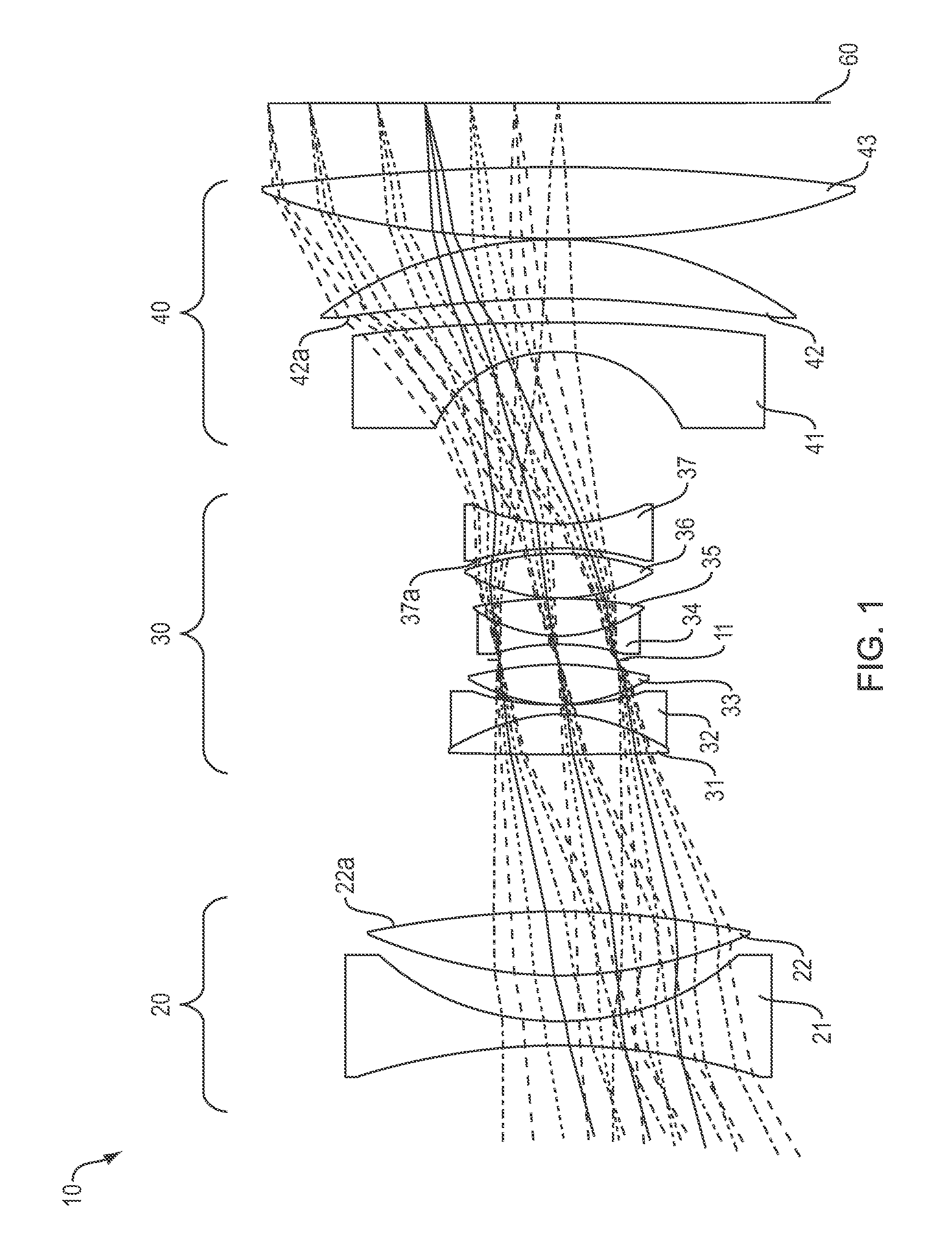
[0122]FIG. 1 is a cross-sectional illustration of the lens 10 of the present invention. The lens 10 includes a first optical group 20, a second optical group 30 and a third optical group 40 in order from the object to the image plane. The aperture stop 11 is positioned inside the second optical group 30. An image of a distant object is formed on a focal plane array 60. In embodiments, the focal plane array incorporates CMOS with micro lenses, 2×2 Bayer filter geometry, and 1.8 Giga pixels. In other applications the image surface 60 may constitute CCD or a direct viewing screen.

[0123]In the embodiment of FIG. 1 the first optical group 20 has an overall positive optical power and is configured to receive light from a remote object and to direct the converged light onto the second optical group 30. The first optical group 20 includes two optical elements 21 and 22, having negative and positive optical powers respectively. As seen in FIG. 1, the first optical element 21 of the first opt...

second embodiment

[0155]FIG. 8 is a cross-sectional illustration of the lens 100 of the present invention. This embodiment is essentially identical to the embodiment of FIG. 1, except for the specific relations that the optical elements satisfy. In particular, the lens 100 includes a first optical group 200, a second optical group 300 and a third optical group 400 in order from the object to the image plane. The aperture stop 110 is positioned inside the second optical group 300. An image of a distant object is formed on a focal plane array 600. In embodiments, the focal plane array incorporates CMOS with micro lenses, 2×2 Bayer filter geometry, and 1.8 Giga pixels. In other applications the image surface 600 may constitute CCD or a direct viewing screen.

[0156]In the embodiment of FIG. 8 the first optical group 200 has an overall negative optical power and is configured to receive light from a remote object and to direct the diverged light onto the second optical group 300. The first optical group 20...

third embodiment

[0186]FIG. 15 is a cross-sectional illustration of the lens 1000 of the present invention. The lens 1000 includes a first optical group 700, a second optical group 800 and a third optical group 900 in the stated order from the object to the image plane. Aperture stop 80 is positioned inside the second optical group 800. An image of a distant object is formed on a focal plane array 90. In some embodiments, the focal plane array incorporates CMOS with micro lenses, 2×2 Bayer filter geometry, and 1.8 Giga pixels. In other embodiments the image surface 60 incorporates CCD or a direct viewing screen.

[0187]The first optical group 700 has an overall positive optical power and is configured to receive light from the remote object and to direct the converged light onto the second optical group 800. The first optical group 700 includes two optical elements 701 and 702, having negative and positive optical powers respectively. As shown in FIG. 15, the first optical element 701 of the first opt...


PUM


Abstract

A compact, lens suitable for airborne photography and mapping has distortion less than 0.6% and is athermal from −15° C. to +40° C. The lens is near-telecentric to less than 11°, apochromatic over the wavelength range 450 nm-650 nm, and has a full field of view of 60° (high quality field over 53°). The lens can be secondary color corrected. In embodiments, the focal length is 101 mm and the back working distance is more than 10 mm. Embodiments have a focal plane diameter of 104 mm and are compatible for use with a CMOS 1.8 gigapixel multiple FPA. In embodiments, the lens comprises three groups of optical elements, with an aperture located within the second optical group. In some embodiments the first group includes two elements, the second group includes six or seven elements, and the third group include three elements. In embodiments the lens (without window) is less than 180 mm long.

Description

FIELD OF THE INVENTION[0001]The invention relates to optical lenses, and more particularly to low distortion lenses.BACKGROUND OF THE INVENTION[0002]Aerial mapping is a fast growing market for both military and civil applications. Aerial mapping acquires airborne image data using remote sensing and produces highly accurate topographic maps of ground regions of interest. Depending on the application, the topographic data produced by aerial mapping are used for evaluation of the dimensions and content of an observed target.[0003]The ability of aerial mapping to provide comprehensive and detailed topographic information depends largely on the capabilities and features of the imaging lens that is used, including the distortion of the lens (whereby the image shape does not precisely reproduce the object shape, depending on the viewing angle), correction of monochromatic and polychromatic aberrations (including secondary spectrum), telecentricity, and thermal stability of the lens (abilit...

Claims


Application Information

Patent Timeline
Patent Type & Authority Applications(United States)
IPC IPC(8): G02B13/22
CPCG02B13/22G02B13/18G02B9/12
Inventor OSKOTSKY, MARK L.RUSSO, JR., MICHAEL J.
Owner BAE SYST INFORMATION & ELECTRONICS SYST INTERGRATION INC
Why Eureka
Try Eureka