Frequency jittering control circuit and method for a pfm power supply

Active Publication Date: 2013-02-28
RICHTEK TECH
View PDF8 Cites 53 Cited by
  • Summary
  • Abstract
  • Description
  • Claims
  • Application Information

AI Technical Summary

Benefits of technology

[0003]An objective of the present invention is to provide a frequency jittering control circuit and method for a PFM power supply.
[0004]According to the present invention, a frequency jittering control circuit for a PFM power supply comprises a pulse frequency modulator for generating a frequency jittering control signal to switch a power switch and generate an output voltage. In a peak-current mode PFM power supply, the pulse frequency modulator turns on the power switch by triggering the control signal responsive to a first signal, and turns off the power swi

Problems solved by technology

Such a PFM power supply, however, when having a consistent load, has its switching frequency held consistent, and thus still suffers from EMI.
Nev

Method used


Image

  • Frequency jittering control circuit and method for a pfm power supply
  • Frequency jittering control circuit and method for a pfm power supply
  • Frequency jittering control circuit and method for a pfm power supply

Examples


first embodiment

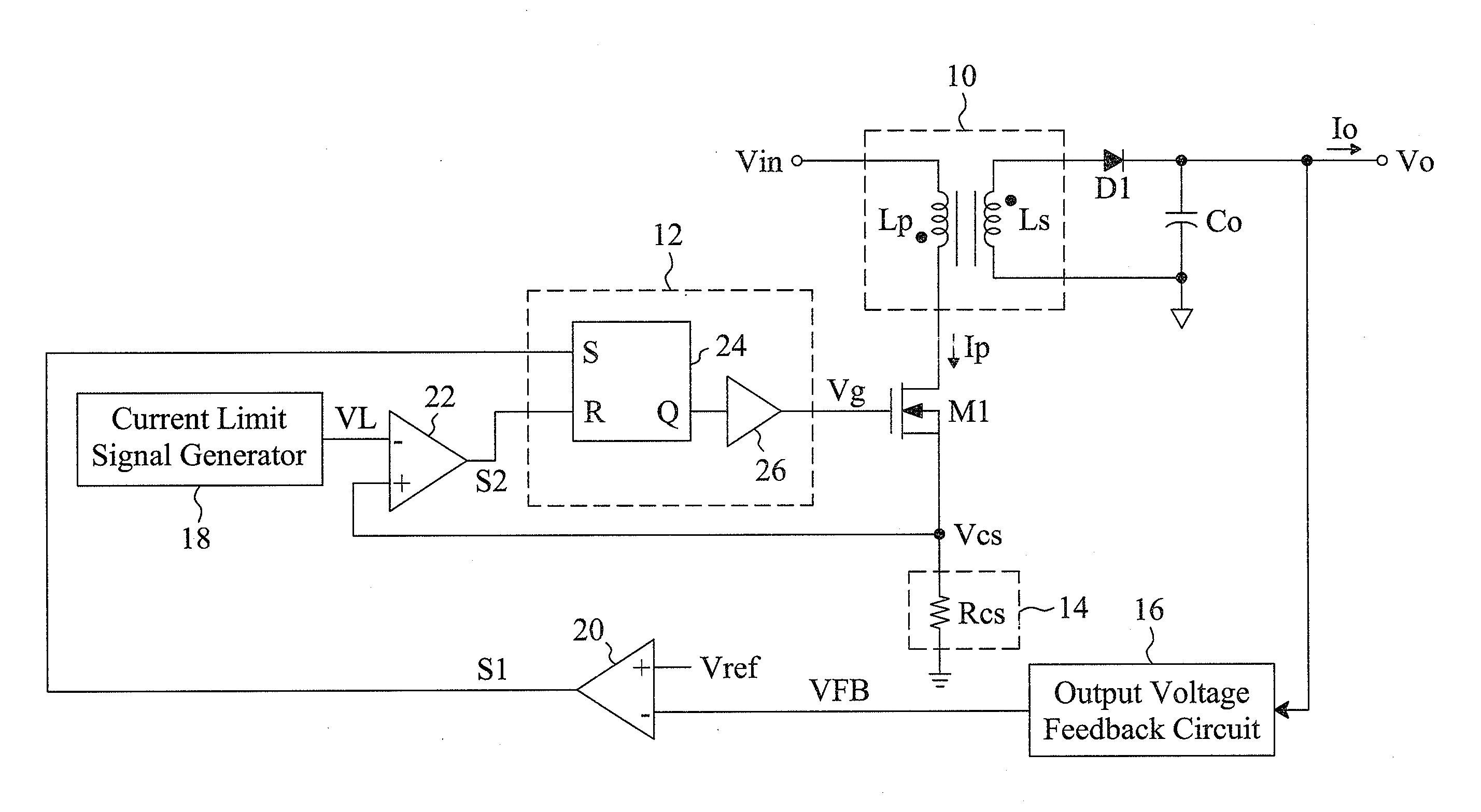
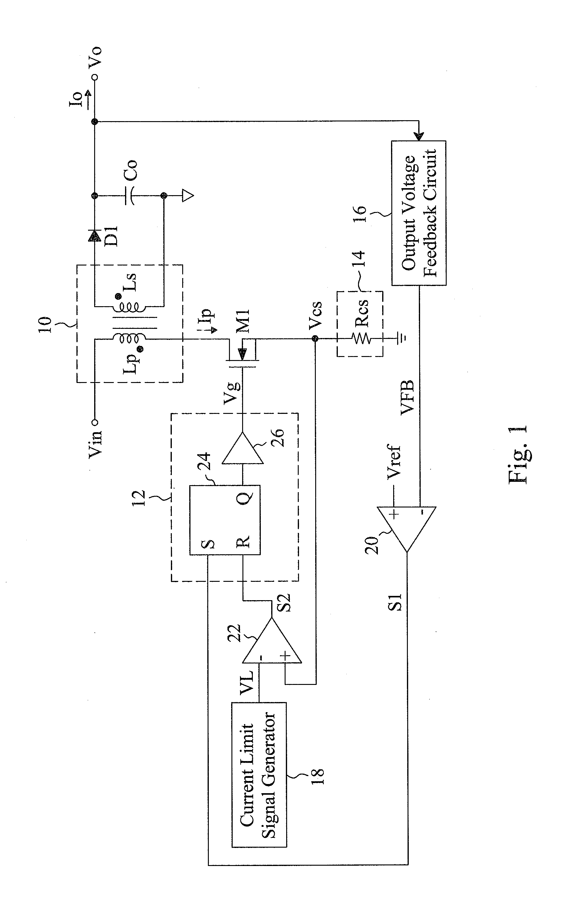
[0021]A first embodiment according to the present invention shown in FIG. 1 is a peak-current mode PFM power supply that comprises a transformer 10, a power switch M1 connected in series to a primary coil Lp of the transformer 10, and a frequency jittering control circuit that generates a frequency jittering control signal Vg for switching the power switch M1, thereby converting an input voltage Vin into an output voltage Vo. In the frequency jittering control circuit, there are a pulse frequency modulator 12 for generating the control signal Vg according to a first signal S1 and a second signal S2, a current detector 14 for detecting a current Ip of the power switch M1 to generate a current sense signal Vcs, an output voltage feedback circuit 16 for detecting the output voltage Vo to generate a feedback signal VFB, a comparator 20 for comparing the feedback signal VFB with a reference voltage Vref to generate the first signal S1, a current limit signal generator 18 for providing a ...

second embodiment

[0023]FIG. 4 is the current limit signal generator 18 of FIG. 1, with the left part identical to that in FIG. 3. The rest of the circuit is composed of a variable resistor 42 and a resistance controller 44. The variable resistor 42 includes a resistor Radj and the resistor Ro connected in series. The resistance controller 44 finely adjusts the resistor Radj to change the resistance of the variable resistor 42, thereby jittering the current limit signal VL. The resistance controller 44 may be realized by a counter or a random number generator.

[0024]The embodiment shown in FIG. 1 jitters the switching frequency by jittering the second signal S2, but the other embodiment can jitter the switching frequency by jittering the first signal S1. As the embodiment shown in FIG. 5, the first signal S1 is delayed by a programmable delay circuit 46 for a period of time before it is sent to the pulse frequency modulator 12. A delay time controller 48 adjusts the delay time of the programmable dela...


PUM


Abstract

A frequency jittering control circuit for a PFM power supply includes a pulse frequency modulator to generate a frequency jittering control signal to switch a power switch to generate an output voltage. The frequency jittering control circuit jitters an input signal or an on-time or off-time of the pulse frequency modulator to jitter the switching frequency of the power switch to thereby improve EMI issue.

Description

FIELD OF THE INVENTION[0001]The present invention is related generally to a switching mode power supply (SMPS) and, more particularly, to pulse frequency modulation (PFM) power supply.BACKGROUND OF THE INVENTION[0002]Electro-magnetic interference (EMI) is known as a critical issue in designing a switching power supply, and is typically improved by spread-spectrum approaches that improve EMI by jittering the switching frequency of the power supply. Existing pulse width modulation (PWM) power supply devices, as those disclosed in U.S. Pat. Nos. 5,929,620, 6,249,876 and 7,289,582, mainly accomplish spectrum-spreading by jittering the frequency of the oscillator and in turn jittering the switching frequency of the power supply. A PFM power supply is a variable-frequency system whose switching frequency varies with its load, so is less subject to EMI. Such a PFM power supply, however, when having a consistent load, has its switching frequency held consistent, and thus still suffers from ...

Claims


Application Information

Patent Timeline
IPC IPC(8): H02M3/335
CPCH02M3/33507H02M1/44H03K7/08H03K2005/00019H02M3/28H02M1/08H02M3/156H02M3/33515H02M3/33523H02M3/33546H02M1/0009H02M3/1566
Inventor PAN, JIUN-HUNGTANG, CHIEN-FUCHEN, ISAAC Y.
Owner RICHTEK TECH
Why Eureka
Try Eureka