Memory refresh methods, memory section control circuits, and apparatuses

a memory section and control circuit technology, applied in the field of volatile semiconductor memory, can solve the problems of large unwanted power consumption, gate-induced diode leakage current, and large unwanted current consumption

Active Publication Date: 2013-02-28
MICRON TECH INC
View PDF2 Cites 36 Cited by
  • Summary
  • Abstract
  • Description
  • Claims
  • Application Information

AI Technical Summary

Problems solved by technology

A performance issue associated with the use of such a word line driver is gate-induced diode leakage (GIDL) current.
GIDL currents may arise when the pFET of a word line driver experiences a relatively significant gate-to-drain voltage such that current leaks from the nwell to the drain of the pFET when the transistor is operating in an “off” state.
Because numerous word line drivers may be used simultaneously in a memory system, GIDL current can result in substantial unwanted power consumption, even in inactive sections of memory.
Like GIDL currents, this frequent charging and discharging between the reduced voltage and the increased voltage can lead to unwanted consumption of current.

Method used


Image

  • Memory refresh methods, memory section control circuits, and apparatuses
  • Memory refresh methods, memory section control circuits, and apparatuses
  • Memory refresh methods, memory section control circuits, and apparatuses

Examples


Embodiment Construction

[0013]Certain details are set forth below to provide a sufficient understanding of embodiments of the invention. However, it will be clear to one having ordinary skill in the art that embodiments of the invention may be practiced without these particular details. Moreover, the particular embodiments of the present invention described herein are provided by way of example only and should not be used to limit the scope of the invention to these particular embodiments. In other instances, well-known circuits, control signals, timing protocols, and software operations have not been shown in detail in order to avoid unnecessarily obscuring the invention.

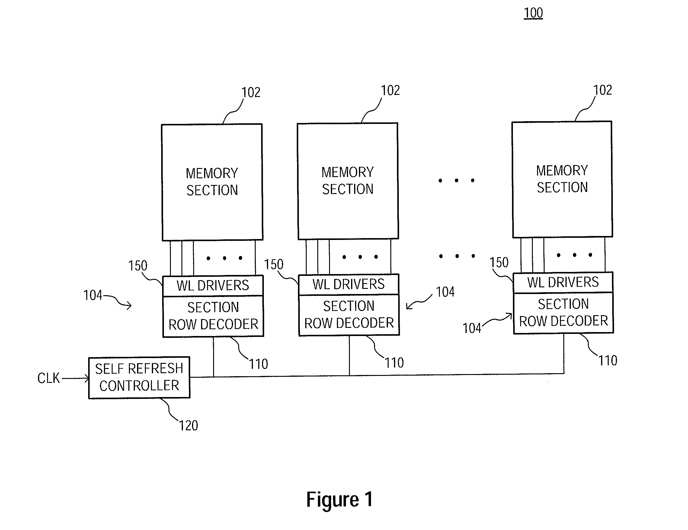
[0014]FIG. 1 illustrates a block diagram for an apparatus in the form of a memory bank 100 according to an embodiment of the invention. The memory bank 100 may include a plurality of memory sections 102 and a corresponding plurality of memory section control circuits 104. Memory sections 102 may each comprise a plurality of rows of memory...


PUM


Abstract

Apparatuses, memory section control circuits, and methods of refreshing memory are disclosed. An example apparatus includes a plurality of memory sections and a plurality of memory section control circuits. Each memory section control circuit is coupled to a respective one of the plurality of memory sections and includes a plurality of access line drivers, each of which includes a plurality of transistors having common coupled gates. During an operation of the apparatus a first voltage is provided to the commonly coupled gates of the transistors of at least some of the access line drivers of the memory section control circuit coupled to an active memory section and a second voltage is provided to the commonly coupled gates of the transistors of the access line drivers of the memory section control circuit coupled to an inactive memory section control circuit, wherein the first voltage is greater than the second voltage.

Description

TECHNICAL FIELD[0001]Embodiments of the present invention relate generally to volatile semiconductor memory, and more particularly in one or more of the illustrated embodiments, to reduction of power consumption in memory devices by regulating a word line driver voltage during self-refresh operations.BACKGROUND OF THE INVENTION[0002]Contemporary memory devices typically include an array of memory cells arranged in rows and columns. Memory cells of each row are accessed by activating a corresponding access line often referred to as a word line. The word line may be activated by a word line driver responsive to decoding a corresponding row address with a row address decoder.[0003]Word line drivers typically comprise a p-channel field effect transistor (pFET) and an n-channel field effect transistor (nFET) coupled together at their respective drains and gates, forming a complementary FET output stage coupled to the word line at the drains of the transistors. The source of the pFET can ...

Claims


Application Information

Patent Timeline
Patent Type & Authority Applications(United States)
IPC IPC(8): G11C11/402G11C8/08
CPCG11C8/08G11C8/10G11C11/406G11C11/402G11C2211/4065G11C2211/4067G11C5/147G11C11/4085G11C11/40615
Inventor PORTER, JOHN DAVIDKIM, GI-HONG
Owner MICRON TECH INC
Why Eureka
Try Eureka