
Compensating devices and methods for detecting and compensating for sampling clock offset

a compensation device and clock offset technology, applied in the field of compensating devices and methods for sampling clock offset, can solve problems such as oscillator variations, synchronization errors that may occur, and sensitive to synchronization errors

Active Publication Date: 2013-02-28
MEDIATEK INC
View PDF3 Cites 3 Cited by
  • Summary
  • Abstract
  • Description
  • Claims
  • Application Information

AI Technical Summary

Benefits of technology

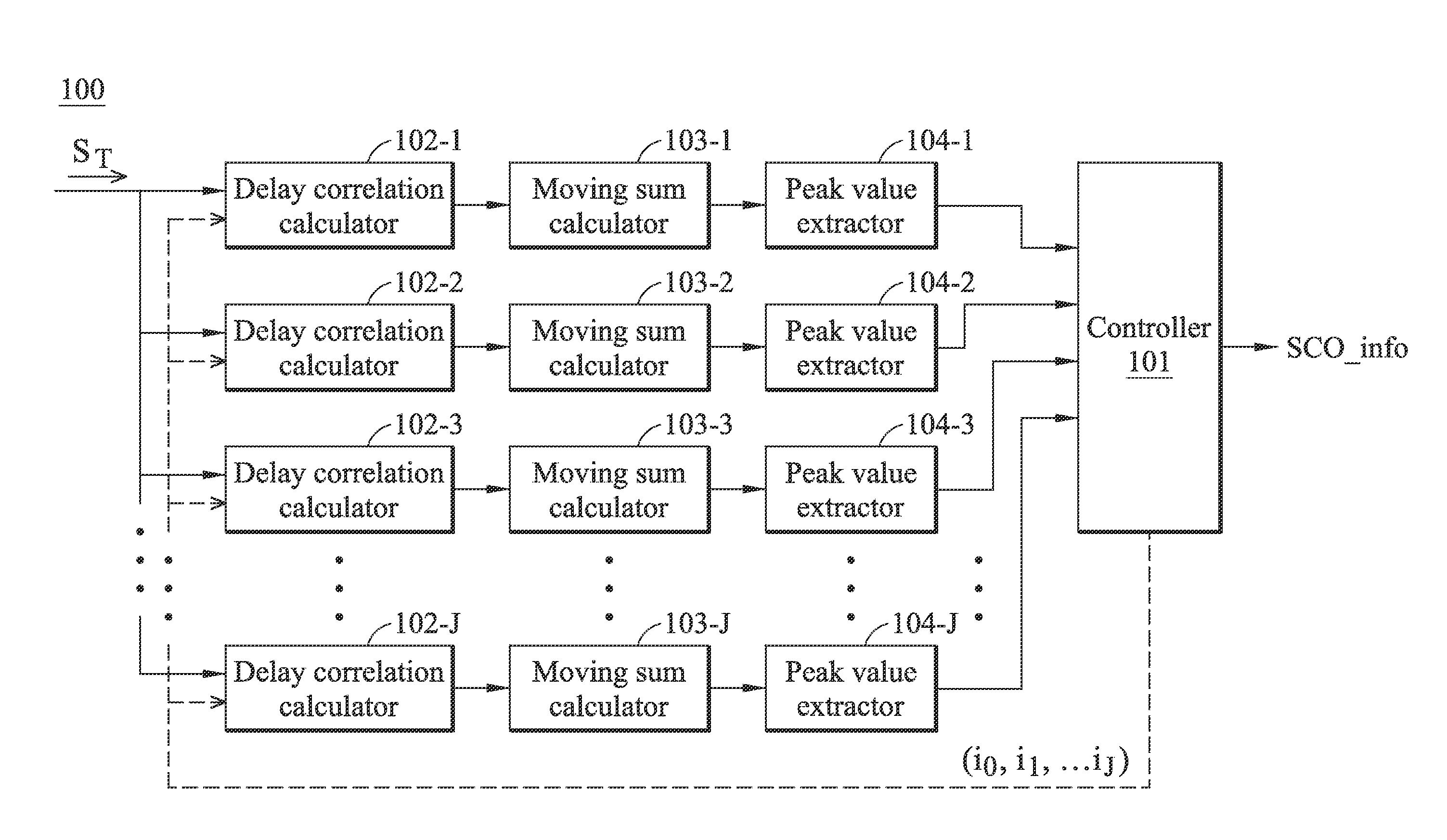
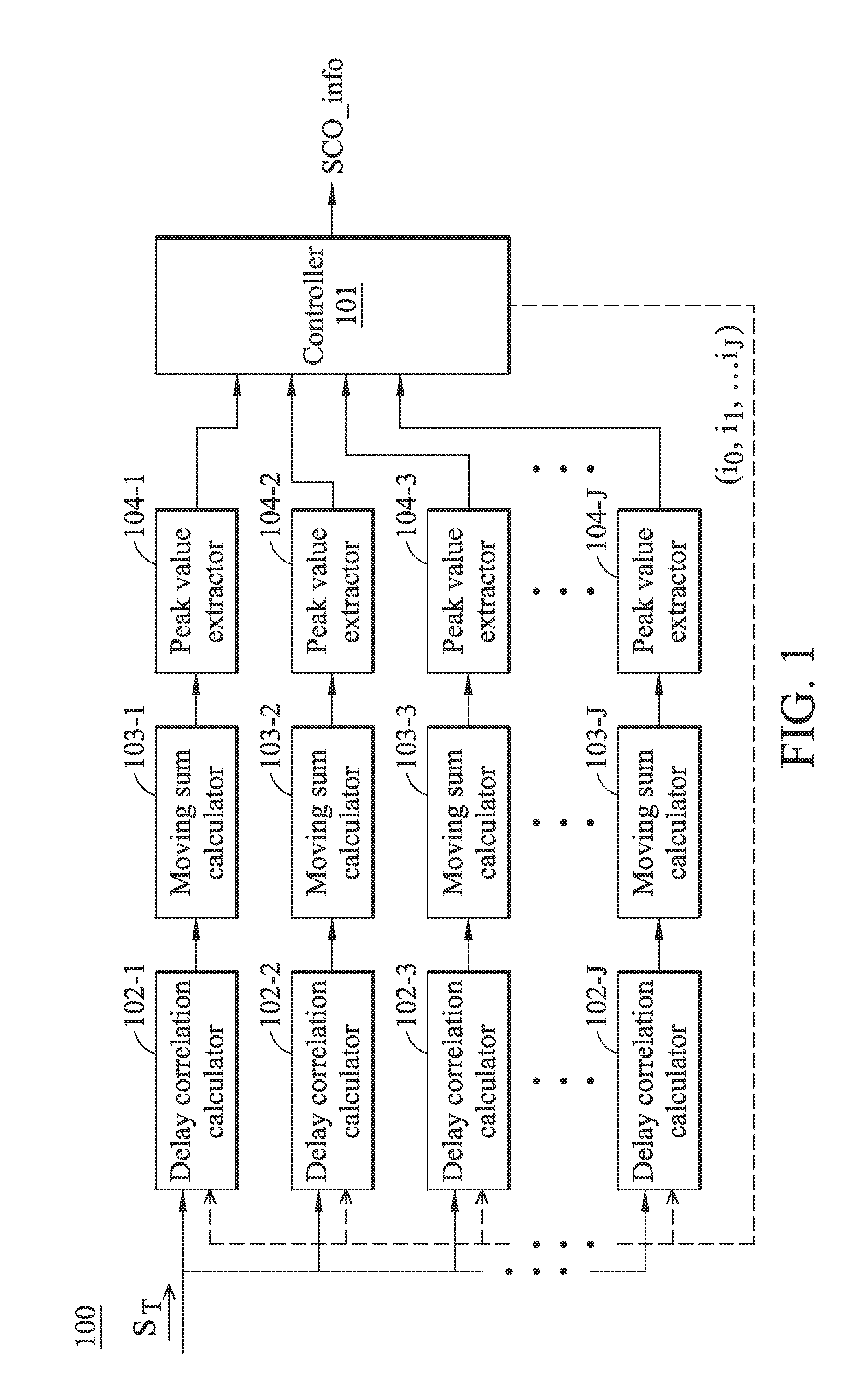
This patent describes a compensating device and method for detecting and compensating for a sampling clock offset in a receiver. The device uses a sampling clock offset detector to calculate correlation coefficients between a time domain signal and delayed versions of the signal, and a controller to detect the sampling clock offset based on the maximum correlation coefficient sum. The device then compensates for the sampling clock offset on the signal generated in the receiver's signal processing path. The technical effect of this patent is to improve the quality and reliability of data transmission in high-speed wireless communication systems.

Problems solved by technology

However, it is sensitive to synchronization errors.
Synchronization errors may occur because of carrier frequency offset and sampling clock mismatches (also called sampling clock offset (SCO)).
For example, oscillator variations because of tuning oscillator instabilities or other errors can occur at both the transmitter and receiver sides.
Synchronization errors may also be caused by Doppler shifts induced by a channel.
Serious synchronization errors may cause two effects: symbol timing drift and inter-carrier interference.

Method used


Image

  • Compensating devices and methods for detecting and compensating for sampling clock offset
  • Compensating devices and methods for detecting and compensating for sampling clock offset
  • Compensating devices and methods for detecting and compensating for sampling clock offset

Examples


Embodiment Construction

[0019]The following description is of the best-contemplated mode of carrying out the invention. This description is made for the purpose of illustrating the general principles of the invention and should not be taken in a limiting sense. The scope of the invention is best determined by reference to the appended claims.

[0020]According to the concept of the invention, the sampling clock offset (SCO) may be detected in the time domain (i.e. before performing Fast Fourier Transform (FFT)) at an OFDM receiver by using a repeat waveform, which is repeatedly carried in an OFDM signal. In an embodiment of the invention, the repeat waveform may be the waveform carried in the guard interval of the OFDM signal. For example, for the DTV system, the repeat waveform may be the waveform in the guard interval since the waveform carried in the guard interval is a repeat waveform of the tail part of an OFDM symbol. In another embodiment of the invention, the repeat waveform may be the preamble of an ...


PUM


Abstract

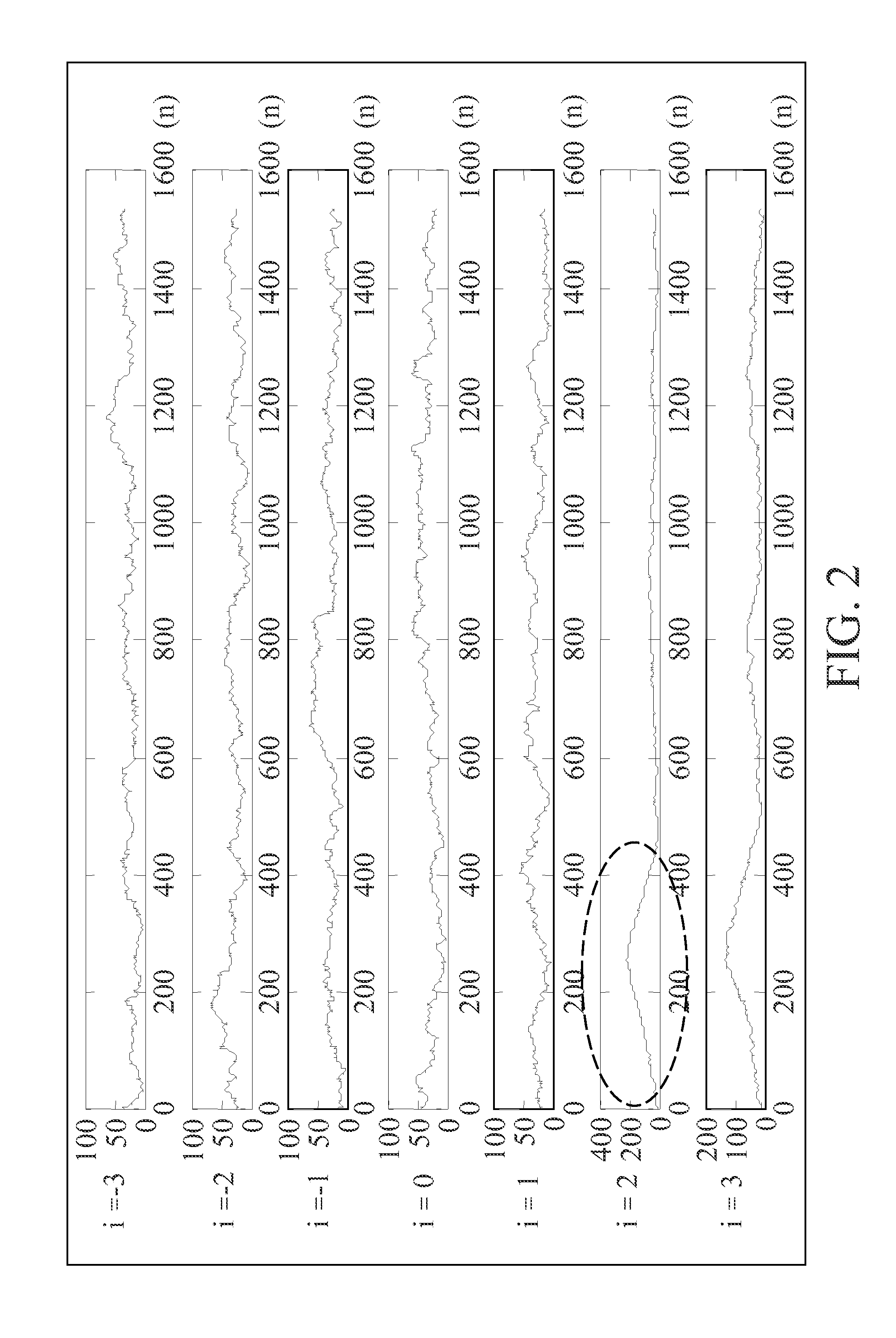
A compensating device for detecting and compensating for a sampling clock offset in a receiver. An SCO detector includes multiple calculation paths and a controller. Each calculation path receives a time domain signal and a hypothetic offset, calculates correlation coefficients between the time domain signal and a delayed version of the time domain signal according to a predetermined delay and the hypothetic offset, calculates correlation coefficient sums according to the correlation coefficients, and extracts a maximum correlation coefficient sum for the hypothetic offset from the correlation coefficient sums. The controller is coupled to the calculation paths for providing different hypothetic offsets to each calculation path and detects the SCO according to the maximum correlation coefficient sums obtained from the calculation paths. An SCO compensator receives the SCO and compensating for the SCO on a signal generated in a signal processing path of a receiver.

Description

BACKGROUND OF THE INVENTION[0001]1. Field of the Invention[0002]The invention relates to an OFDM receiver, and more particularly to an OFDM receiver capable of detecting and compensating for sampling clock offset (SCO).[0003]2. Description of the Related Art[0004]Orthogonal frequency division multiplexing (OFDM) is a promising technology for broadband transmission due to its high spectrum efficiency, and its robustness to the effects of multipath fading channels. However, it is sensitive to synchronization errors.[0005]Synchronization errors may occur because of carrier frequency offset and sampling clock mismatches (also called sampling clock offset (SCO)). For example, oscillator variations because of tuning oscillator instabilities or other errors can occur at both the transmitter and receiver sides. Synchronization errors may also be caused by Doppler shifts induced by a channel. Serious synchronization errors may cause two effects: symbol timing drift and inter-carrier interfer...

Claims


Application Information

Patent Timeline
IPC IPC(8): H04L27/06
CPCH04L27/2657H04L27/2676H04L27/2672H04L27/2671
Inventor CHEN, YI-CHUAN
Owner MEDIATEK INC
Learn More