Transition channel of a turbine unit

a turbine unit and channel technology, applied in the direction of motors, air transportation, climate sustainability, etc., can solve the problems of high noise level of the turbine, inconvenient operation, and insufficient flow of secondary flows, so as to improve the flow, increase the life of the blading, and reduce the effect of nois

Inactive Publication Date: 2013-02-28
MTU AERO ENGINES GMBH
View PDF0 Cites 53 Cited by
  • Summary
  • Abstract
  • Description
  • Claims
  • Application Information

AI Technical Summary

Benefits of technology

[0022]Most of the application cases will be covered if one to five flow splitter blades are arranged between the support ribs. Preferably, the total number of support ribs and flow splitter blades taken together is chosen such that excitations of fundamental modes of the rotor blades in the operating range by perturbation harmonics of the transition channel are prevented or reduced.
[0023]The present invention enables an improvement of the flow thanks to a partial division of functions: the number, shape and arrangement of the long and heavy support ribs

Problems solved by technology

Such a geometry of the support ribs, however, leads to intense secondary flows.
Such strong three-dimensional secondary flows are detrimental to the main flow; in particular, they may limit the maximum possible

Method used


Image

  • Transition channel of a turbine unit
  • Transition channel of a turbine unit
  • Transition channel of a turbine unit

Examples


Embodiment Construction

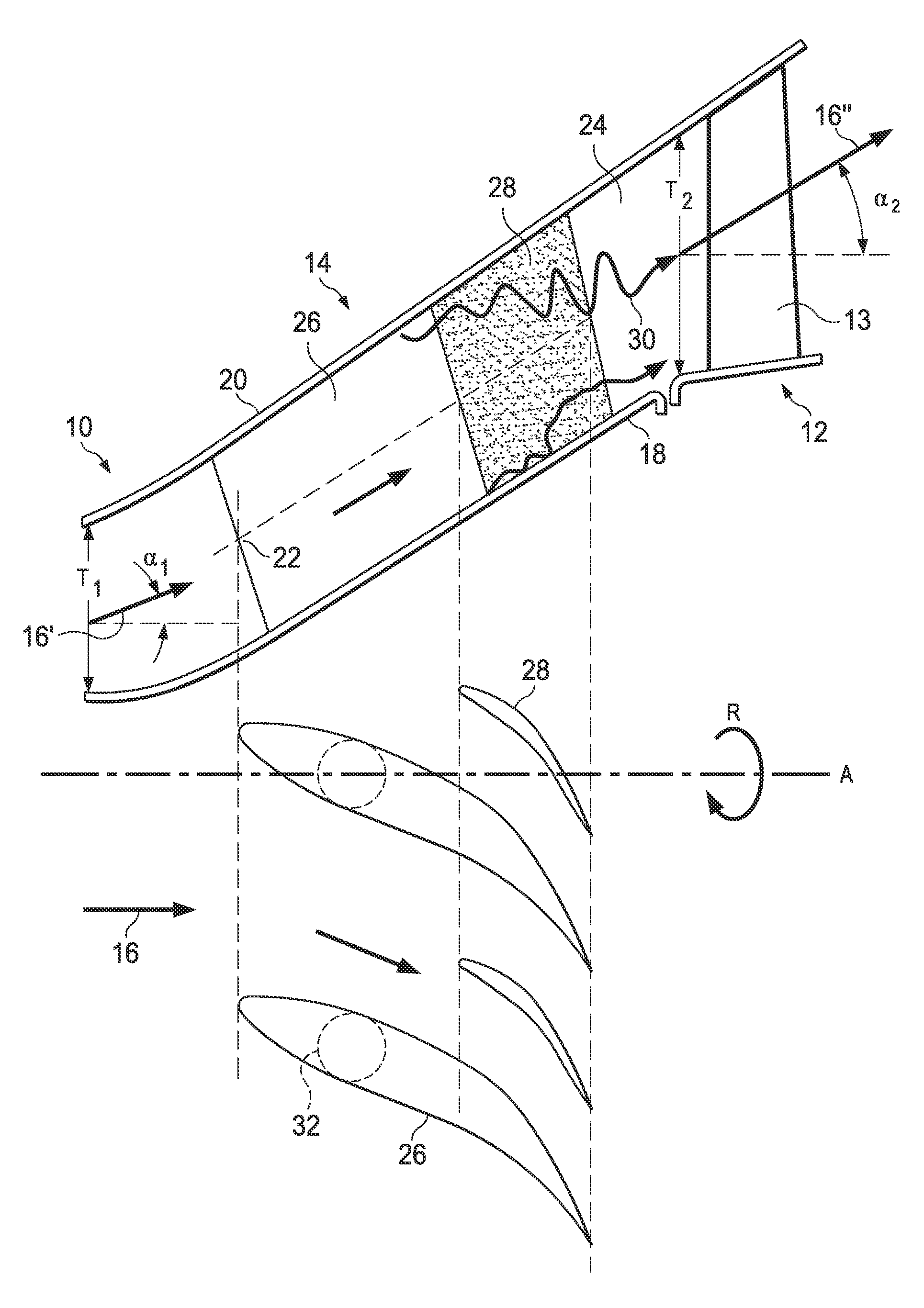
[0033]FIG. 1 shows, as an example, a transition channel between two components of a turbine, hereinafter turbine components, in axial half-section and median section (top part of the drawing) and in a planar developed view or profile section (bottom part of the drawing).

[0034]According to the representation in FIG. 1, a flow process between a high-pressure turbine 10 and a low-pressure turbine 12 is determined by a transition channel 14. The flow process is indicated by an arrow 16.

[0035]The transition channel 14 has an inner wall or envelope surface 18 and an outer wall or envelope surface 20, which together define an annular cross section. In particular, an entry cross section 22 is defined at the start of the transition channel 14 and an exit cross section 24 at the outlet of the transition channel 14. It should be noted that the transition channel 14 is configured stationary with respect to the turbine axis A or an otherwise not represented turbine housing, while the high-pressu...


PUM


Abstract

A transition channel for a turbine unit with at least two components is configured as a flow channel from one component of a first pressure to a component of a second pressure. The transition channel has support ribs, extending between envelope surfaces of the transition channel and having a profile that is configured for the deflecting of a flow from an inlet cross section to an outlet cross section of the transition channel. Flow splitter blades are arranged between the support ribs, having a smaller relative profile thickness than the support ribs and/or a shorter axial design depth or profile chord length than the support ribs. Thanks to the integration of the slim and/or short flow splitter blades (tandem blades), it is possible to largely dissipate parasite secondary flows.

Description

CROSS-REFERENCE TO RELATED APPLICATIONS[0001]This application claims benefit of German Patent Application No. 102011115499.3, filed Aug. 29, 2011, entitled ÜBERGANGSKANAL EINE TURBOAGGREGATS, the specification of which is incorporated herein in its entirety.TECHNICAL FIELD[0002]The invention concerns a transition channel between components of a turbine unit, as well as a turbine unit and a jet engine, especially an aircraft engine, with such a transition channel.BACKGROUND[0003]A transition channel, such as can be arranged in particular between a high-pressure turbine and a low-pressure turbine or—when the turbine has a three-piece design—between high and medium-pressure turbine and / or medium and low-pressure turbine, determines the flow to the first rotor of the downstream turbine. The transition or diversion channel (“turning mid turbine frame”, TMTF) generally guides the flow in annular or envelope fashion from an upstream flow cross section to a downstream flow cross section tha...

Claims


Application Information

Patent Timeline
IPC IPC(8): F01D1/02F02C3/00
CPCF01D9/06F01D9/041F01D5/146Y02T50/673Y02T50/60
Inventor HOEGER, MARTINKOERBER, KAIENGEL, KARL
Owner MTU AERO ENGINES GMBH
Why Eureka
Try Eureka