Pleural Pressure Indicator

a pleural pressure and indicator technology, applied in the field of pleural pressure indicators, can solve the problems of increased field mortality, life-threatening pneumothorax, and compromise of circulatory system, so as to simplify the diagnosis task and eliminate the possibility of open pneumothorax

Inactive Publication Date: 2013-02-28
ISG AG
View PDF9 Cites 3 Cited by
  • Summary
  • Abstract
  • Description
  • Claims
  • Application Information

AI Technical Summary

Benefits of technology

[0009]The key component to the device is the use of a temperature dependent resistor based sensor for detecting air flow. The device bears the ability to demonstrate sensed air flow through the use of indicators which could include: LEDs (Light Emitting Diodes) an LCD (Liquid Crystal Display), or a sound emitter all of which would be oriented to demonstrate air flow and its relative magnitude in a linearly stepping sequence. A check valve is included to manage the release of the accumulated intrathoracic pressure and eliminate the possibility of an open pneumothorax. Remaining components provide power and signal reporting through a circuit. All components are contained in a sleek, pen-like housing that supports concurrent manipulation, indication, and reading of the device.
[0010]The pleural pressure indicator will provide a lightweight, compact, field-ready solution to medical users attempting to diagnose patients with symptoms of pneumothorax or subsequent tension pneumothorax. The object of the invention is to simplify the task of diagnosis, thereby eliminating the guess work and inaccuracies associated with impromptu techniques.

Problems solved by technology

The tension pneumothorax is a life threatening condition that results from the accumulation of air within the pleural cavity, subsequent to chest injury from penetrating trauma.
This subsequent increase of intrathoracic pressure defines the development of the tension pneumothorax and leads to an increase in field mortality.
Additionally, where accumulated air produces pressure sufficient enough to reduce cardia preload this results in circulatory compromise.

Method used


Image

  • Pleural Pressure Indicator
  • Pleural Pressure Indicator
  • Pleural Pressure Indicator

Examples


Embodiment Construction

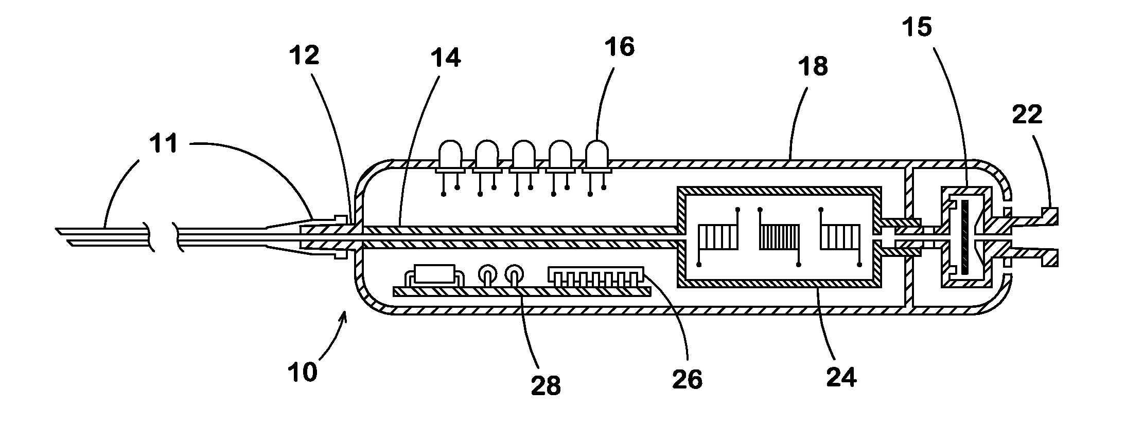
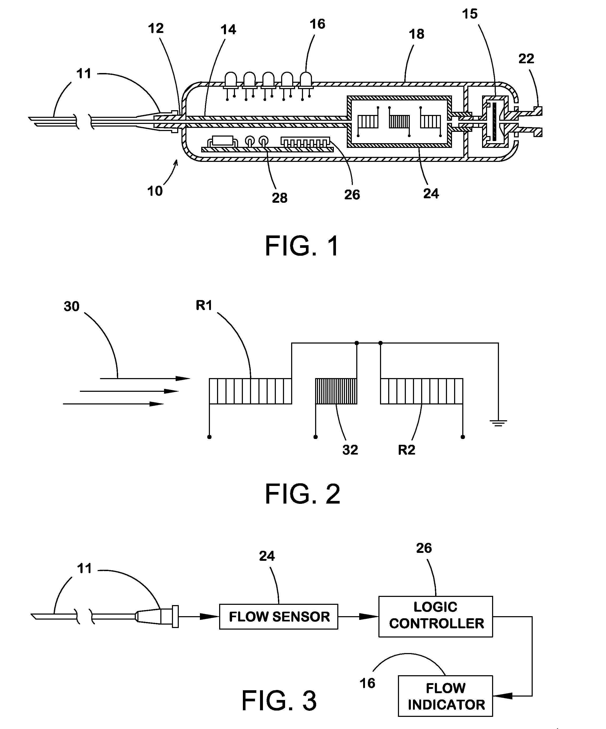
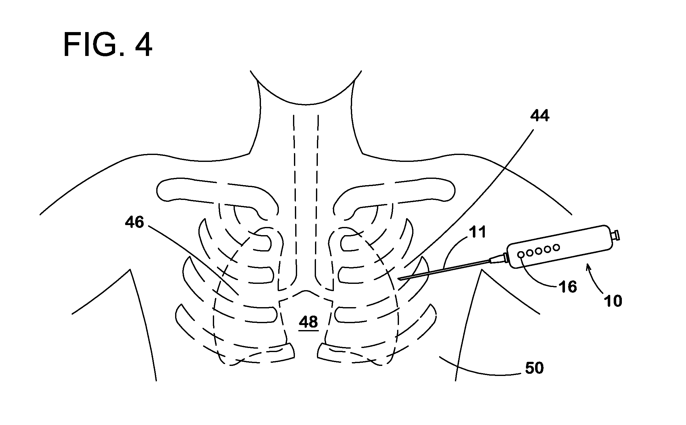
[0015]As shown in FIG. 1, the current invention 10 comprises of a handheld body 18 containing several features to allow proper operation and interface with the user. The features include inlet 12 and outlet 22 ports, user activated check valve 15, a temperature dependent resistor based sensor 24, software based logic controller 26, indicator 16, and a protective case 18 integrating the previous features. When the device is held in hand by the user, the proximal end with the integral inlet 12 is designed to mate with a medical catheter 11 for sensing positive pressure or lack thereof in a patient's pleural cavity through the proper use of a catheter over the medical needle 11 intercostally 44 by means of air flow 30.

[0016]According to the inlet 12 feature, the inlet feature is included to interface the main body 18 of the invention containing the sensing element 24 to a catheter 11 that is properly located on the patient as shown in FIG. 4.

[0017]According to both the inlet 12 and out...


PUM


Abstract

The pleural pressure indicator is a diagnostic device for use in the field where more sophisticated electronics are not permissible, though early detection of pneumothoraces relative to penetrating chest trauma is paramount to survival.When the device is used with the placement of a needle thoracentesis, it serves the user by indicating flow to and from the chest cavity. This indication is supportive of the user's diagnosis of the patients' respiratory condition.When a patient is suffering from a tension pneumothorax, positive air flow will be indicated by the device. The user can switch the check valve in the device flow path to manage intrathoracic pressure relief, therapeutically reducing the tension pneumothorax, increasing survivability.The pleural pressure indicator is a compact, portable, handheld device that is simple to operate, compatible with needles, catheters, and syringes and simple to read for a quick indication of a patient's condition.

Description

BACKGROUND OF THE INVENTION[0001]The pleural pressure indicator is a handheld diagnostic device for use in the field where more sophisticated electronic devices are not available. Utilized by a trained individual, the pleural pressure indicator is a diagnostic and therapeutic tool able to support the field diagnosis of a tension pneumothorax.[0002]The tension pneumothorax is a life threatening condition that results from the accumulation of air within the pleural cavity, subsequent to chest injury from penetrating trauma. As the casualty breathes, air escapes from the injury site at the lung and is allowed to accumulate within the pleural cavity. Air accumulates with each breath the casualty takes and is unable to return through the lung tissue where the injury site serves as a one way valve. As accumulated air increases so does pressure within the chest wall which inhibits the patient's attempts to produce negative pressure during inhalation. This subsequent increase of intrathorac...

Claims


Application Information

Patent Timeline
Patent Type & Authority Applications(United States)
IPC IPC(8): A61B5/03
CPCA61B5/03A61B2562/0271A61B5/6848A61B5/08
Inventor LEVEQUE, ANDRE MARCELVONDERHARR, JACOB GREGORY
Owner ISG AG
Why Eureka
Try Eureka