Position detection system and position determination method

a detection system and position detection technology, applied in the direction of anti-theft devices, process and machine control, instruments, etc., can solve the problems of increasing the difficulty of wiring in the vehicle, and the increase in the weight of the wire harness, so as to accurately determine accurate detection of the position, and accurate determination of the position of the radio wave transmitting body

Active Publication Date: 2013-02-28
OMRON AUTOMOTIVE ELECTRONICS CO LTD
View PDF1 Cites 13 Cited by
  • Summary
  • Abstract
  • Description
  • Claims
  • Application Information

AI Technical Summary

Benefits of technology

[0014]Therefore, in the vehicle including the plurality of electronic control devices that conduct radio communication with each other, the method for accurately determining the position of the radio wave transmitting body using the other electronic control device can be provided.
[0015]As described above, according to one or more embodiments of the invention, a position detection system and a position determination method, which accurately detect the position of the radio wave transmitting body without providing many dedicated antennae that transmit and receive the information using the radio signal in the electronic control device that controls the device of the vehicle, can be provided in the vehicle control system in which the vehicle includes the plurality of electronic control devices. As a result, the position of the radio wave transmitting body can accurately be determined without separately providing the antenna that transmits and receives the information using the radio signal. Additionally it is not necessary to dispose the wire harness between the electronic control devices in order to transmit and receive the information. Therefore, there is a margin in a space of the vehicle, and weight reduction is also achieved.

Problems solved by technology

However, the ECUs are disposed in many places in the vehicle, and the number of wire harnesses, such as an electric power line connecting a battery and each ECU and a communication line (such as a CAN and a LIN) connecting the ECUs, is increased to enlarge a wiring space, which may result in difficulty in performing wiring in the vehicle.
An increase in weight of the wire harness may also occur.
However, in the related art, in order to accurately detect the position of the FOB, it is necessary to dispose the receiver and the antenna in each position of the vehicle, and therefore it is necessary to install the wiring between the receiver and the antenna and the ECU, which results in wiring space being enlarged to increase a wire harness weight.

Method used


Image

  • Position detection system and position determination method
  • Position detection system and position determination method
  • Position detection system and position determination method

Examples


Embodiment Construction

[0023]Hereinafter, embodiments of the present invention will be described with reference to the drawings. In embodiments of the invention, numerous specific details are set forth in order to provide a more thorough understanding of the invention. However, it will be apparent to one of ordinary skill in the art that the invention may be practiced without these specific details. In other instances, well-known features have not been described in detail to avoid obscuring the invention.

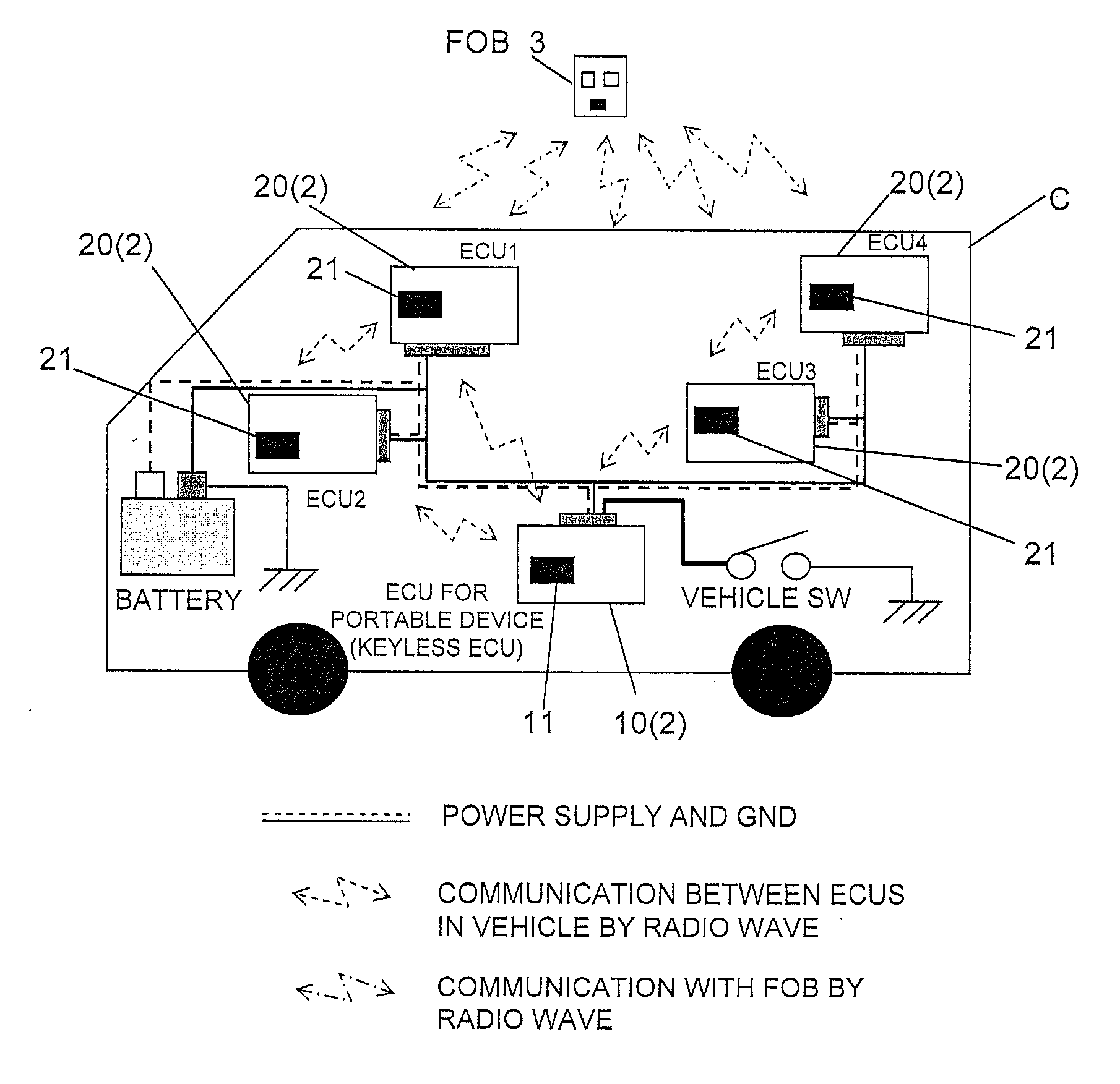
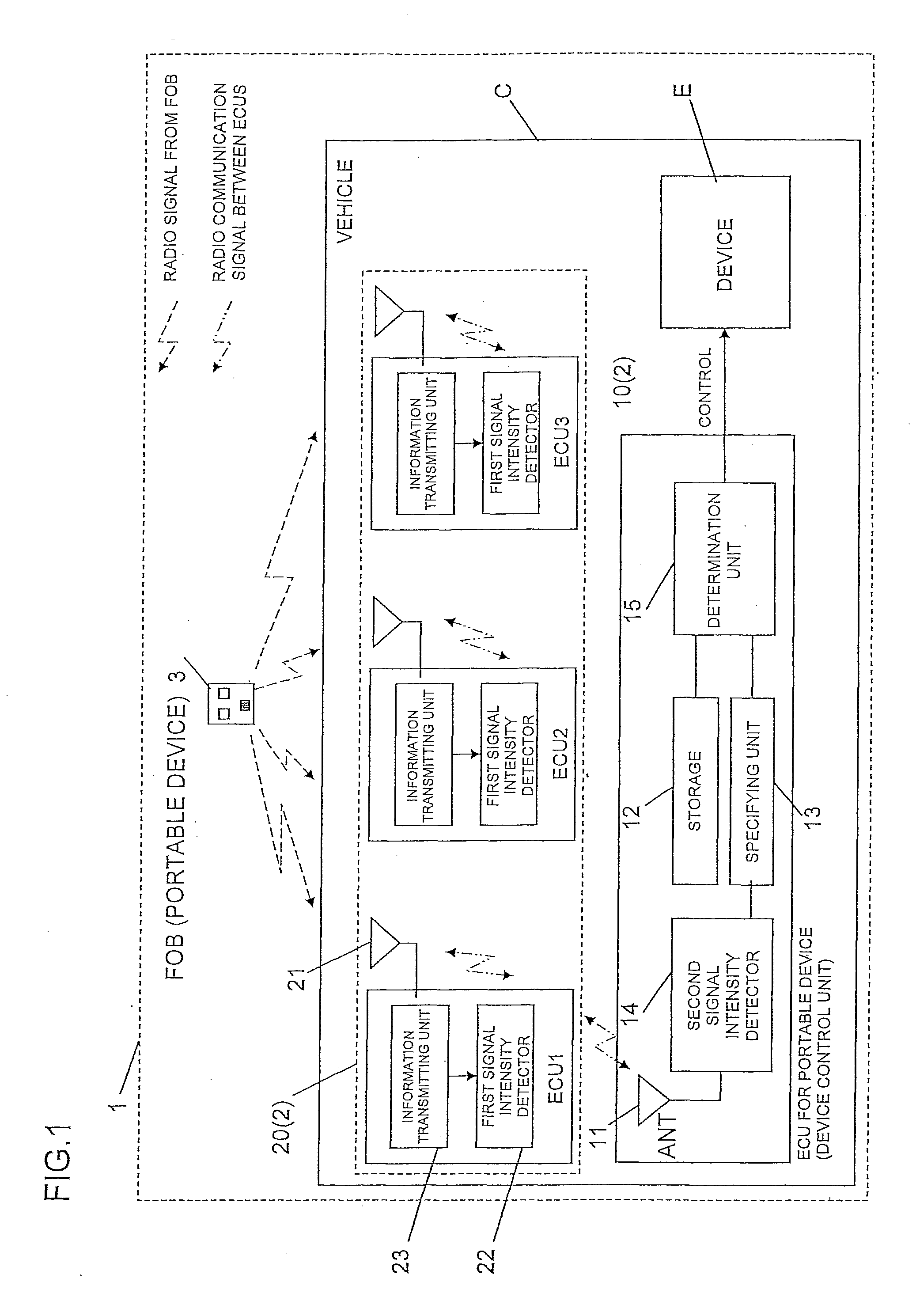
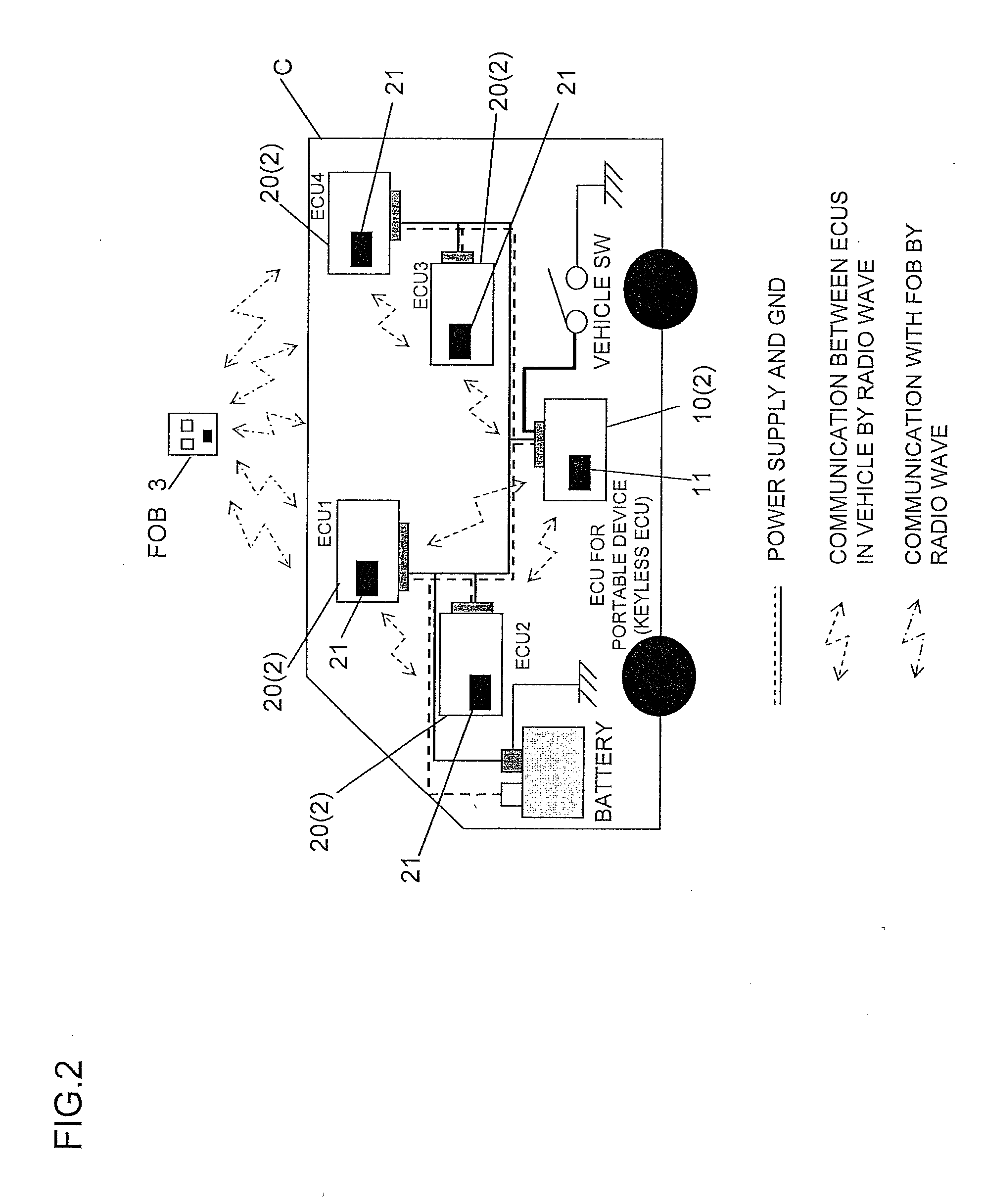
[0024]FIG. 1 is a block diagram illustrating a position detection system 1 according to one or more embodiments of the invention. The position detection system 1 includes an electronic control device 2 that is provided in a vehicle C and a portable device 3 (also referred to as an FOB) that is the radio wave transmitting body, which transmits information using a radio signal. The portable device 3 is not limited to a product possessed by a user of the vehicle. For example, the portable device 3 may be a c...


PUM


Abstract

A radio-wave-transmitting-body position detection system in a vehicle system has a plurality of electronic control devices that are included in a vehicle, and a radio wave transmitting body that transmits a radio signal to the plurality of electronic control devices. The electronic control devices conduct communication with each other using the radio signal. Each electronic control device includes a first electronic control device that conducts communication with the other electronic control device and the radio wave transmitting body using the radio signal, and controls a device included in the vehicle based on a content of the radio signal transmitted from the radio wave transmitting body. The electronic control devices except the first electronic control device include a first transmitting/receiving unit that transmits and receives the radio signal.

Description

TECHNICAL FIELD[0001]The present invention relates to a position detection system and a position determination method, particularly to a position detection system and a position determination method in a vehicle control system including a plurality of electronic control devices that are provided in a vehicle and a portable device that transmits information using a radio signal.RELATED ART[0002]Nowadays, a vehicle is controlled by many electronic control devices (hereinafter also referred to as “ECUs”) including engine control, such as a fuel injection amount, vehicle driving control, such as a transmission, braking control, such as an ABS (Antilock Brake System), and vehicle-body control, such as a door, a power window, and an air-bag. Communication between the ECUs and sharing of information are required to properly control each unit of the vehicle, and the ECUs are connected to each other through a network to construct an in-vehicle network system.[0003]However, the ECUs are dispo...

Claims


Application Information

Patent Timeline
Patent Type & Authority Applications(United States)
IPC IPC(8): B60R16/023G01S5/14
CPCB60R25/245
Inventor SUZUKI, TAKAYUKIKAWASHIMA, HIDEMITSU
Owner OMRON AUTOMOTIVE ELECTRONICS CO LTD
Why Eureka
Try Eureka