Method of Pattern Recognition for Artificial Intelligence

a pattern recognition and artificial intelligence technology, applied in the field of parallel processing, can solve the problems of labor intensive applications including certain pattern recognition applications that perform ineffectively, disadvantageous limitation of pattern recognition in data processing performance,

Active Publication Date: 2013-02-28
SNYDER STEVEN HOWARD
View PDF2 Cites 2 Cited by
  • Summary
  • Abstract
  • Description
  • Claims
  • Application Information

AI Technical Summary

Benefits of technology

[0017]Another preferred embodiment of the present invention which is applied for pattern recognition applies a version of the digitally-based methods of pattern recognition mentioned hereinbefore with the addition of steps for modifying the values of one or more of the parameters of a pattern input for comparison in terms of, for example, size, position, and / or rotation in order to compare an input pattern with stored patterns when the values of one or more of the parameters of the pattern input for comparison can vary from the stored pattern in terms of, as in this example, size, position, and / or rotation.
[0018]Another preferred embodiment of the present invention which is applied for pattern recognition applies a version of the digitally-based methods of pattern recognition mentioned hereinbefore with the addition of steps for modifying the values of one or more of the parameters of the stored patterns in terms of, for example, size, position, and / or rotation in order to compare an input pattern with the stored patterns when the values of one or more of the parameters of the pattern input for comparison can vary from the stored pattern in terms of, as in this example, size, position, and / or rotation.

Problems solved by technology

Such methods of pattern recognition disadvantageously limit the performance of the processing of data due to machine cycles which consume fetch and execution times and consequentially cause a bottleneck.
In effect, labor intensive applications including certain pattern recognition applications perform ineffectively.

Method used


Image

  • Method of Pattern Recognition for Artificial Intelligence
  • Method of Pattern Recognition for Artificial Intelligence
  • Method of Pattern Recognition for Artificial Intelligence

Examples


Embodiment Construction

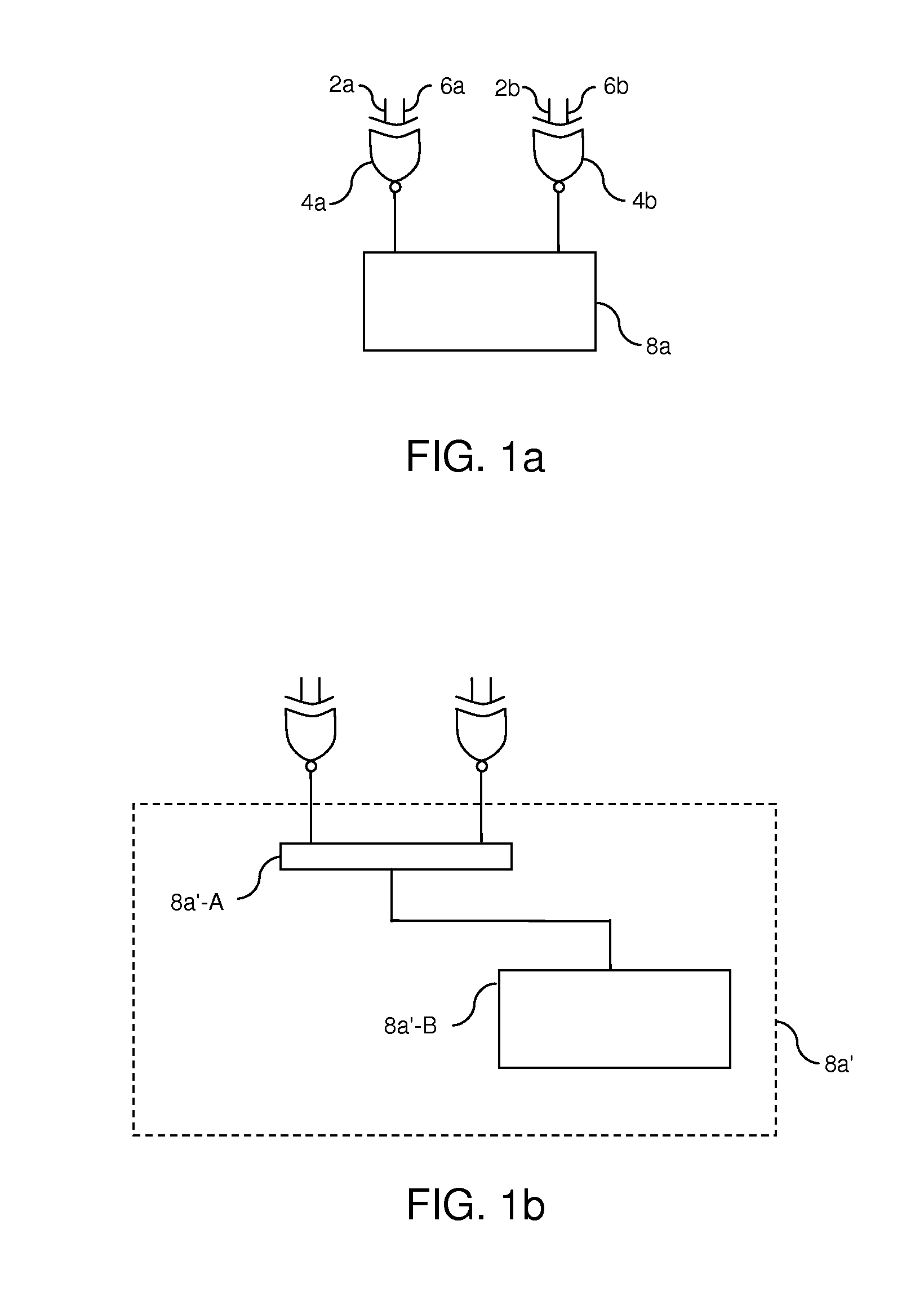
[0029]FIG. (1a) is a schematic view of a first preferred embodiment of the present invention which is applied for pattern recognition which comprises the following steps:

[0030]1) Storing a pattern of data by applying an electrical input, e.g. a binary logic level (1) input, or the absence of electrical input, e.g. a binary logic level (0) input, to inputs (2a) and (2b) comprised by exclusive-nor logic gates (4a) and (4b), wherein a pattern of data is stored in parallel;

[0031]2) Comparing an input pattern of data with the stored pattern of data by applying an electrical input, e.g. a binary logic level (1) input, or the absence of electrical input, e.g. a binary logic level (0) input, to inputs (6a) and (6b) comprised by exclusive-nor gates (4a) and (4b), such that exclusive-nor gates (4a) and (4b) each produce an electrical output, e.g. a binary logic level (1) output, or the absence of electrical output, e.g. a binary logic level (0) output, according to the logic of their respecti...


PUM


Abstract

Invention for pattern recognition and artificial intelligence comprising:
1) storing data in parallel by applying a logic level (1) input or a logic level (0) input to one input of each of at least two exclusive-nor logic gates;
2) comparing data in parallel by applying a logic level (1) input or a logic level (0) input to the other input of each of the exclusive-nor gates, wherein each exclusive-nor gate produces a logic level (1) output when both inputs have the same datum input, and each exclusive-nor gate produces a logic level (0) output when both inputs have different datum input; and
3) measuring the outputs of the exclusive-nor logic circuits collectively with a measuring apparatus, wherein the percentage of the pattern input for comparison which matches the pattern of data stored in the exclusive-nor gates is directly proportional to the magnitude of the collective output of the exclusive-nor gates.

Description

BACKGROUND OF THE INVENTION[0001]1. Field of the Invention[0002]In general, the present invention pertains to methods of parallel processing. More specifically, the present invention pertains to methods of pattern recognition including, in particular, methods of pattern recognition for artificial intelligence.[0003]2. Prior Art of the Invention[0004]Prior art pertinent to the present invention includes methods of processing data for pattern recognition. More specifically in the pertinent prior art, conventional computers typically apply hardware and software in a serial process which implements one or more microprocessors and instruction set architecture for pattern recognition. Such methods of pattern recognition disadvantageously limit the performance of the processing of data due to machine cycles which consume fetch and execution times and consequentially cause a bottleneck. In effect, labor intensive applications including certain pattern recognition applications perform ineffe...

Claims


Application Information

Patent Timeline
Patent Type & Authority Applications(United States)
IPC IPC(8): G06N5/02
CPCG06F7/02G06K9/00986G06F7/607G06F7/5013G06V10/955
Inventor SNYDER, STEVEN HOWARD
Owner SNYDER STEVEN HOWARD
Why Eureka
Try Eureka