Transitional Mode High Speed Rail Systems

a high-speed rail system and transitional mode technology, applied in the direction of rope railways, locomotives, roads, etc., can solve the problems of limited passenger transportation, inefficient trains, and serious limitations of current high-speed rail systems

Inactive Publication Date: 2013-03-07
WFK & ASSOC
View PDF20 Cites 14 Cited by
  • Summary
  • Abstract
  • Description
  • Claims
  • Application Information

AI Technical Summary

Benefits of technology

[0011]It is an object of the present disclosure to provide a high Speed rail system that does not have the disadvantages associated with current high speed rail systems, such as bullet trains.

Problems solved by technology

Most high speed trains travel on standard gauge rail road beds and are limited to transporting passengers.
Current high speed rail systems have serious limitations.
The train is inefficient because it requires the same personnel and same amount of energy to complete a scheduled trip whether it has one passenger or 500 passengers.
High speed rail trains also suffer from limited flexibility, as the train can only travel where the rails go.
Often the rail infrastructure is constructed through interstate highway medians, thereby making stations harder to access and requiring major highway and overpass construction.
This is an expensive and inefficient way to deliver electric energy to the locomotives.
High speed rail trains also have little to differentiate between each other.
But such speeds are less relevant if the train has a station stop every few miles.
Yet, there are also drawbacks to having fewer stops between large cities.
However, with limited station stops, the trains will now receive revenue from fewer passengers.
Higher speed means increased aerodynamic resistance, less efficiency, more noise, more hazards, and ultimately higher costs.
Furthermore, the cost of constructing these high speed rail systems (which may include track infrastructure, stations, locomotives and passenger cars) is very high.
High speed rail systems often fail because it is typically difficult for commuters to get to the stations, find a place to park, and travel on the trains' schedule.
High speed rail systems also often leave commuters stranded at remote stations.
As a result of the lack of popularity, high speed trains always require heavy government subsidies to make up for revenue shortfalls.
High speed rail infrastructure does not add capacity to existing interstate highways.
Interstate highways have become increasingly crowded and sometimes overcrowded.
Often times traffic becomes so heavy it comes to a standstill.
A third problem addressed by the present disclosure relates to heavy freight hauling that is now done by diesel tractor trailers.
Yet another problem is that heavy loaded tractor trailers are estimated to cause 90% of the damage requiring road maintenance repairs.
Tractor trailer operators have many other problems to deal with.
Speed limits and traffic congestion create further delays.
The cost of diesel fuel is also increasing just as the costs of gasoline and other fuels.

Method used


Image

  • Transitional Mode High Speed Rail Systems
  • Transitional Mode High Speed Rail Systems
  • Transitional Mode High Speed Rail Systems

Examples


Embodiment Construction

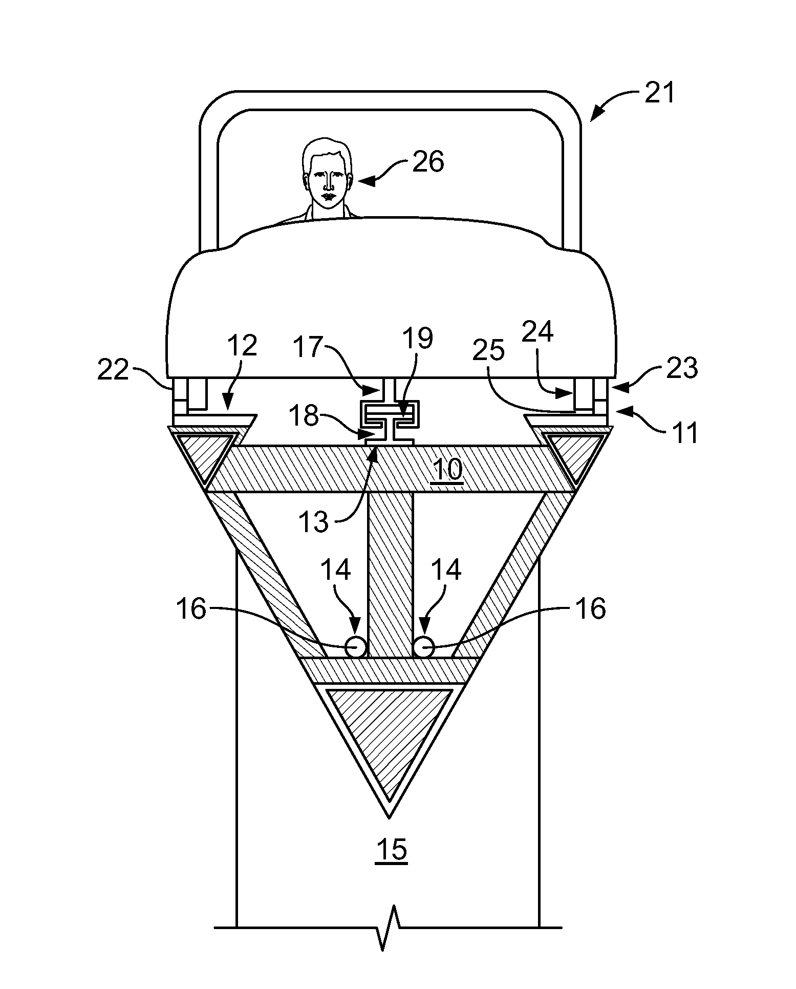
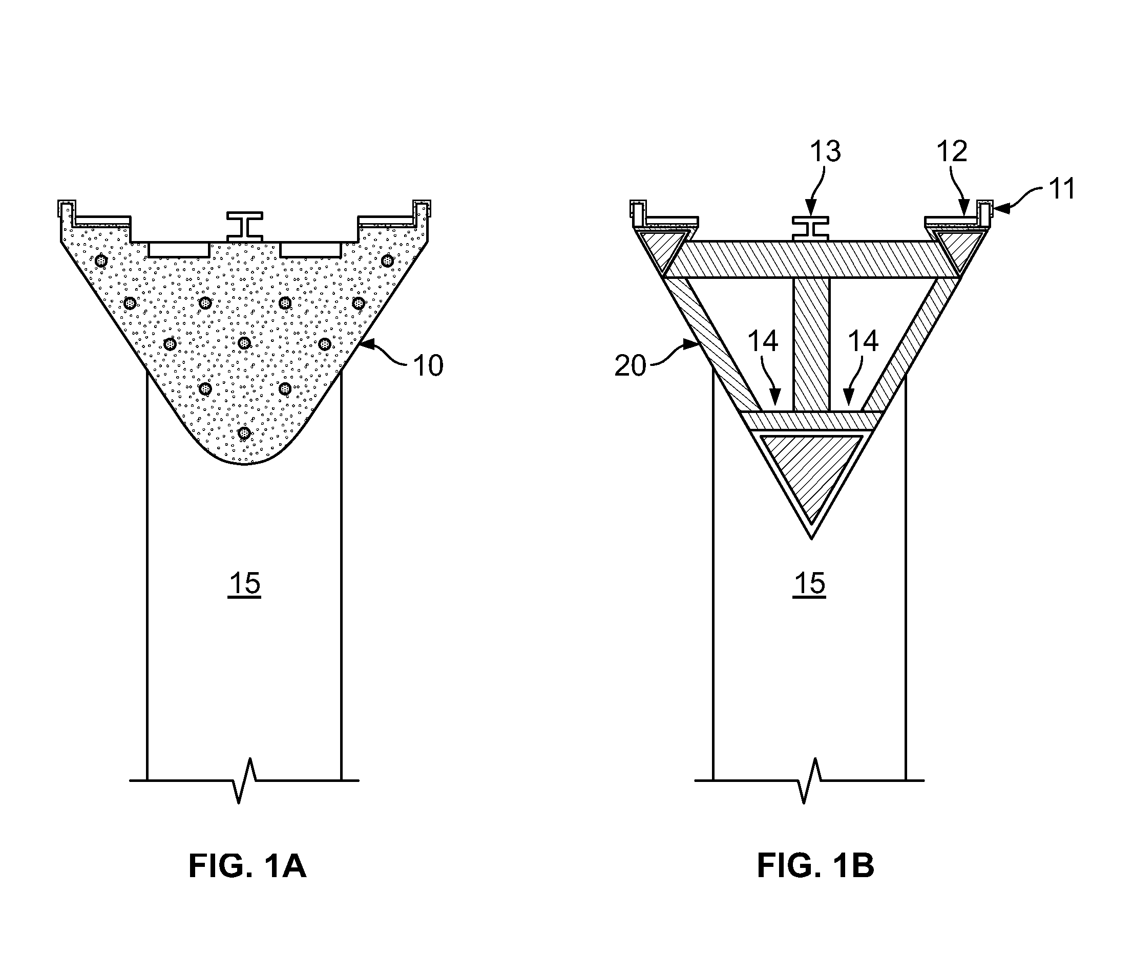
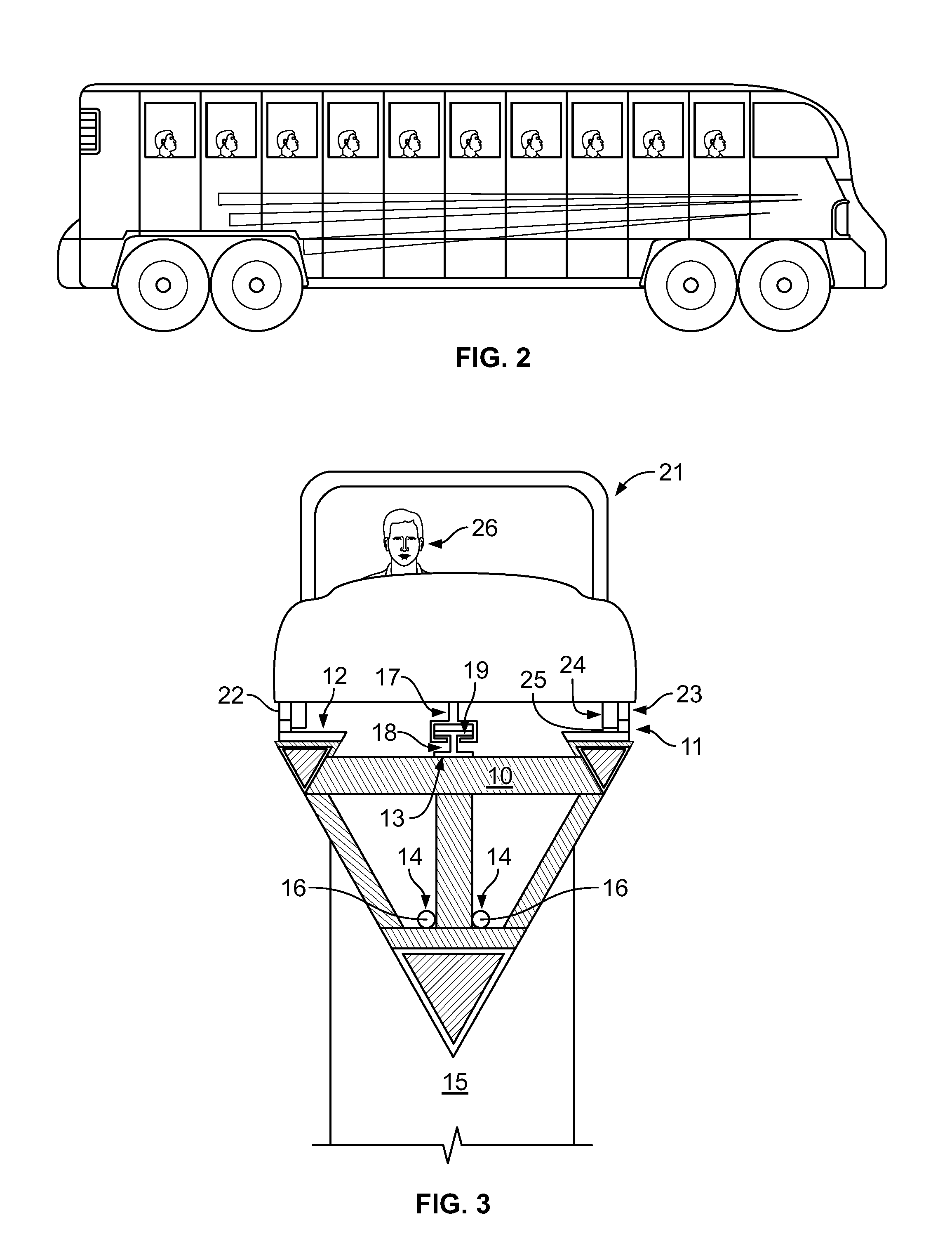
[0043]The present disclosure relates to a transitional mode high speed rail system. The high speed rail infrastructure employed by the system is constructed adjacent a conventional host highway. The infrastructure can be provided adjacent to acceleration / deceleration lanes, or emergency parking / paved shoulder lanes. The various vehicles used by the system include individual, self-powered, self-operating, individual mass passenger transport vehicles similar in size and appearance to municipal buses. These are transitional mode vehicles because they operate as railroad vehicles on the high speed rail infrastructure, but transition to automotive vehicle mode traveling on ordinary paved roads. They are mass passenger transport vehicles because many passengers can be accommodated. Throughout this description these vehicles will be referred to simply as mass passenger transports (or “MPTs”). The various details of the present invention, and the manner in which they interrelate, will be de...


PUM


Abstract

The present disclosure relates to a transitional mode high speed rail system. The high speed rail infrastructure employed by the system is constructed adjacent a conventional host highway. The infrastructure can be provided adjacent to acceleration/deceleration lanes, or emergency parking/paved shoulder lanes. The vehicles used by the system are individual, self-powered, self-operating, individual mass passenger transport vehicles similar in size and appearance to municipal buses. These are transitional mode vehicles because they operate as railroad vehicles on the high speed rail infrastructure, but transition to automotive vehicle mode traveling on ordinary paved roads. They are mass passenger transport vehicles because many passengers can be accommodated.

Description

CROSS-REFERENCE TO RELATED APPLICATIONS[0001]This application claims priority to co-pending provisional patent application Ser. No. 61 / 524,822 filed on Aug. 18, 2011, and entitled “Transitional Mode High Speed Rail.” The contents of this co-pending application are fully incorporated herein for all purposes.TECHNICAL FIELD[0002]This disclosure relates to a high speed rail system. More particularly, the present invention relates to a high speed rail system that employs individually powered passenger cars and that can travel between rail and road infrastructures.BACKGROUND OF THE INVENTION[0003]The present disclosure addresses three distinct transportation related problems. The three problems concern, high speed rail, the interstate highway system, and heavy freight hauling. Traditional high speed rail, also sometimes referred to as bullet trains, are well known in the art. Most high speed trains travel on standard gauge rail road beds and are limited to transporting passengers. Curren...

Claims


Application Information

Patent Timeline
Patent Type & Authority Applications(United States)
IPC IPC(8): B61F13/00B61C3/02B61B5/02B61C13/04E01B25/00B61D1/00
CPCB61C13/04Y02T30/10Y02T30/30B61B3/02Y02T30/00B61B5/02B61C3/00B61F13/00E01B25/00
Inventor KISSEL, JR., WALDEMAR F.
Owner WFK & ASSOC
Why Eureka
Try Eureka