
Motor and washing machine having the same

a technology of motors and washing machines, applied in the field of motors, can solve the problems of increasing manufacturing costs, difficult to and leaking of magnetic flux toward the rotary shaft, so as to improve the performance of the motor and reduce the size of the motor

Inactive Publication Date: 2013-03-07
SAMSUNG ELECTRONICS CO LTD
View PDF10 Cites 53 Cited by
  • Summary
  • Abstract
  • Description
  • Claims
  • Application Information

AI Technical Summary

Benefits of technology

This patent is about a motor design that reduces magnetic leakage and improves motor performance. The motor has a rotor with a barrier hole that reduces the width of magnetic paths, which reduces the amount of magnetic flux that leaks towards the motor shaft. This results in improved motor performance and reduced size for the same power output. The strengthened rotor structure also increases durability, preventing damage during high-speed rotation.

Problems solved by technology

However, in the spoke-type permanent magnet motor, some of the magnetic flux may leak toward the rotary shaft through the cylindrical support of the rotor body.
If the magnetic leakage flux is large, the amount of permanent magnet required to obtain the same power output in the motor increases, thereby increasing the manufacturing cost and making it difficult to reduce the size of the motor.
Meanwhile, in the spoke-type permanent magnet, a portion connecting the core of the rotor to the support is structurally weak, and thus the core of the rotor may be deformed or damaged due to a centrifugal force during a high-speed rotation.

Method used


Image

  • Motor and washing machine having the same
  • Motor and washing machine having the same
  • Motor and washing machine having the same

Examples


Embodiment Construction

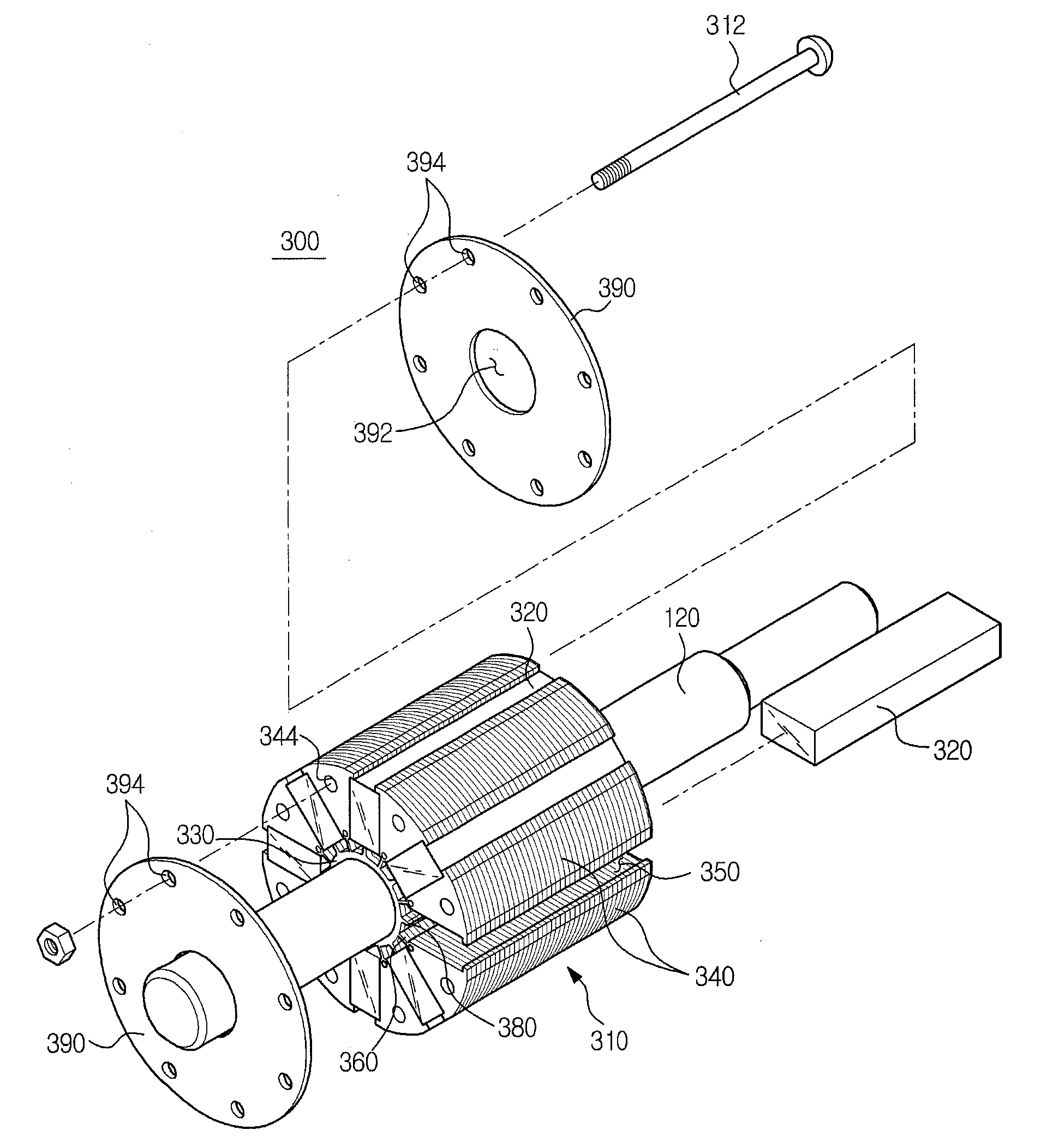
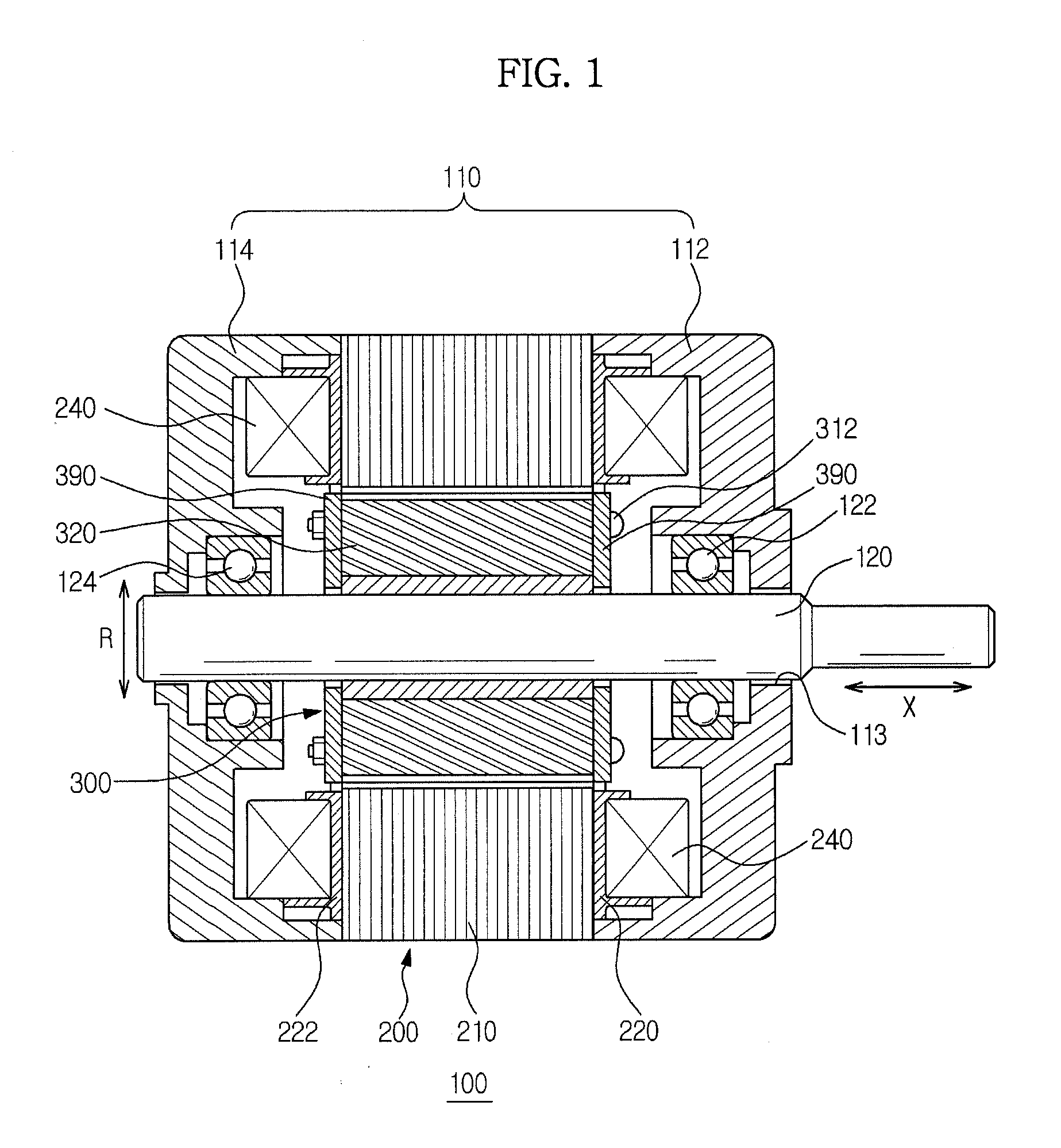
[0058]Reference will now be made in detail to the embodiments of the present disclosure, examples of which are illustrated in the accompanying drawings, wherein like reference numerals refer to like elements throughout. In the following description, a lengthwise direction along a motor shaft will be referred to as an axial direction (X). The direction of circumference of a circle around the motor shaft and the radial direction of a circle around the motor shaft are referred to as a circumferential direction (C) and a radial direction (R), respectively.

[0059]Referring to FIG. 1, a motor 100 includes a motor housing 110 forming an external appearance of the motor 100. The motor housing 110 includes a first housing 112 and a second housing 114 that are separated in the axial direction of the motor 100. The first housing 112 and the second housing 114 are coupled to the stator 200.

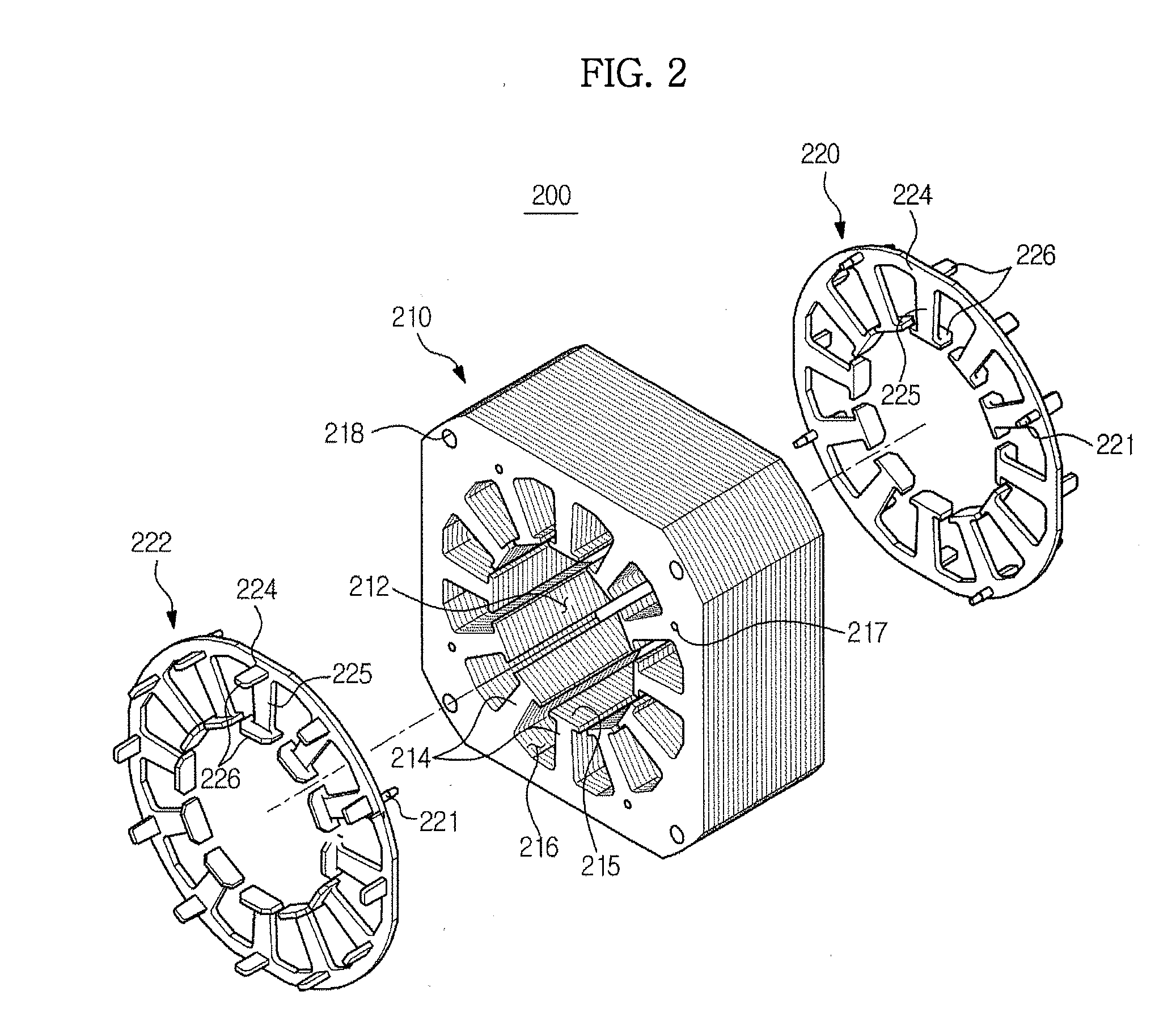
[0060]A stator 200 and a rotor 300 are disposed inside the motor housing 110. The stator 200 is fixed to th...


PUM


Abstract

A motor includes a stator having stator cores, a coil wound around the stator cores, and a rotor disposed at an inner side of the plurality of stator cores. The rotor includes a sleeve, a plurality of rotor cores arranged in a circumferential direction of the rotor, a plurality of bridges arranged to connect the sleeve to each of the plurality of rotor cores, a plurality of permanent magnets provided between the rotor cores to form an interior space with respect to the sleeve while being spaced apart from the sleeve, and a plurality of support protrusions protruding from the sleeve in an outward radial direction of the sleeve to support the plurality of permanent magnets while corresponding to the plurality of permanent magnets, respectively, the plurality of support protrusions being arranged between the bridges while being spaced apart from the bridges in the circumferential direction of the rotor.

Description

CROSS-REFERENCE TO RELATED APPLICATIONS[0001]This application claims the benefit of Korean Patent Applications No. 2011-0090885, filed on Sep. 7, 2011, and No. 2012-0091203, filed on Aug. 21, 2012, in the Korean Intellectual Property Office, the disclosures of which are incorporated herein by reference.BACKGROUND[0002]1. Field[0003]Embodiments of the present disclosure relate to a motor capable of reducing a magnetic flux leakage.[0004]2. Description of the Related Art[0005]A motor is a machine configured to obtain a torque from electrical energy, and is provided with a stator and a rotor. The rotor and the stator are configured to have an electromagnetic interaction with each other such that the motor is rotated by a force between a magnetic field and an electric current flowing through a coil.[0006]A permanent magnet motor, which uses a permanent magnet in generating a magnetic field, is divided into a surface mounted permanent magnet motor, an interior-type permanent magnet motor...

Claims


Application Information

Patent Timeline
Patent Type & Authority Applications(United States)
IPC IPC(8): H02K1/27D06F37/22
CPCH02K1/2773H02K2213/03
Inventor HAN, JIN WOOKIM, YOUNG KWANKIM, DEOK JININ, BYUNG RYEL
Owner SAMSUNG ELECTRONICS CO LTD
Learn More