
Multi-Phase Power Block For a Switching Regulator for use with a Single-Phase PWM Controller

a switching regulator and multi-phase technology, applied in the direction of electric variable regulation, process and machine control, instruments, etc., can solve the problems of complex multi-phase converters implemented using multi-phase pwm controllers, and the cost of implementation is more expensiv

Active Publication Date: 2013-03-07
MICREL
View PDF15 Cites 60 Cited by
  • Summary
  • Abstract
  • Description
  • Claims
  • Application Information

AI Technical Summary

Benefits of technology

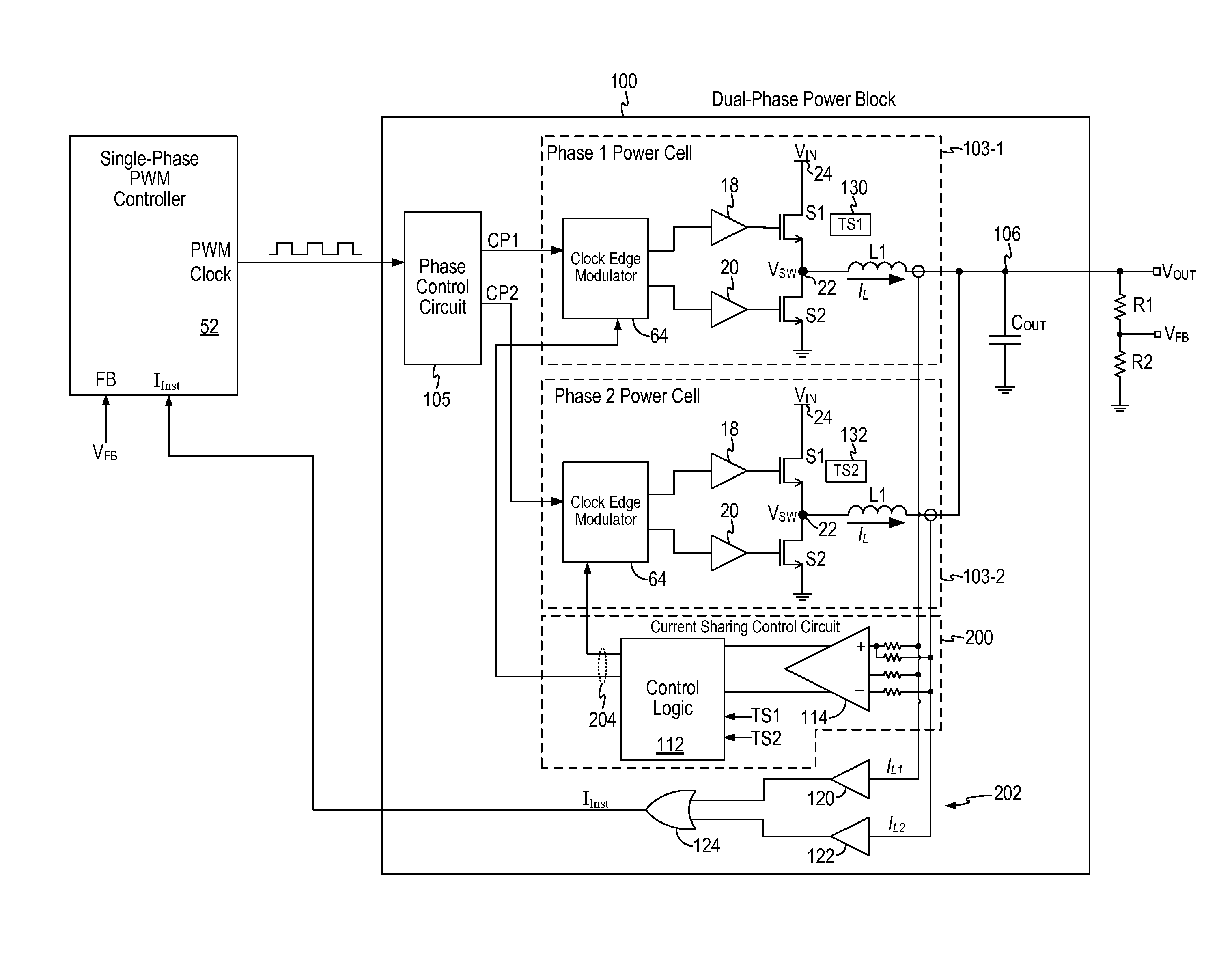
This patent describes a multi-phase power block for a switching regulator. The regulator receives an input voltage and generates a required output voltage. The power block includes a phase control circuit that generates multiple clock signals, which are then sent to power cells in a series. Each cell has power switches that generate a voltage at a common node, which is then sent to the output through an inductor. The current sharing control circuit monitors the current in the inductor and sends out signals to adjust the timing of the clock signals sent to the cells. This helps to balance the current load among the cells. The technical effect of this invention is a more efficient and balanced output from a switching regulator.

Problems solved by technology

Multi-phase converters implemented using multi-phase PWM controller are more complicated and more costly.

Method used


Image

  • Multi-Phase Power Block For a Switching Regulator for use with a Single-Phase PWM Controller
  • Multi-Phase Power Block For a Switching Regulator for use with a Single-Phase PWM Controller
  • Multi-Phase Power Block For a Switching Regulator for use with a Single-Phase PWM Controller

Examples


Embodiment Construction

[0019]In accordance with the principles of the present invention, a multi-phase power block for a switching regulator incorporates multiple power cells, a phase control circuit and a current sharing control circuit. A salient feature of the multi-phase power block is that the multi-phase power block is configured to receive a single phase PWM clock signal so that the multi-phase power block enables multi-phase switching regulator operation using a single-phase PWM controller. The multi-phase power block does not require expensive and complex multi-phase PWM controller. Rather, the multi-phase power block can be coupled with commercially available single-phase PWM controller to realize multi-phase switching regulator operation. A switching regulator configured using the multi-phase power block and a single-phase PWM controller reaps the benefits of multi-phase switching regulator operation without the cost and complexity of a multi-phase PWM controller.

[0020]In embodiments of the pre...


PUM


Abstract

A multi-phase power block for a switching regulator includes a phase control circuit, N power cells and a current sharing control circuit. The phase control circuit is configured to receive a single phase PWM clock signal and generate N clock signals in N phases. Each of the N power cells includes a pair of power switches, gate drivers, a control circuit receiving one of the N clock signals and generating gate drive signals for the gate drivers, and an inductor. The current sharing control circuit is configured to assess the inductor current at the inductor of the N power cells and to generate duty cycle control signals for the N power cells. The duty cycle control signals are applied to the control circuits to adjust the duty cycle of one or more clock signals supplied to the power cells to balance a current loading among the N power cells.

Description

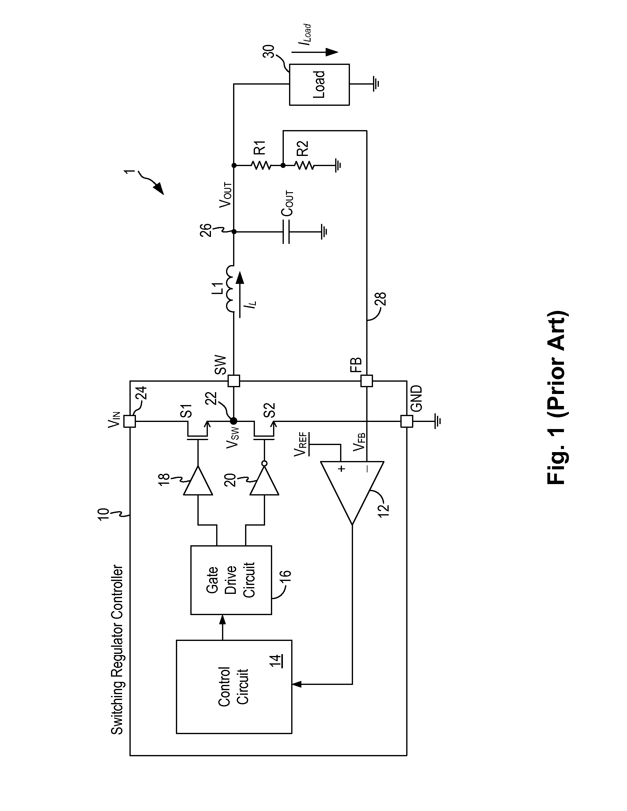
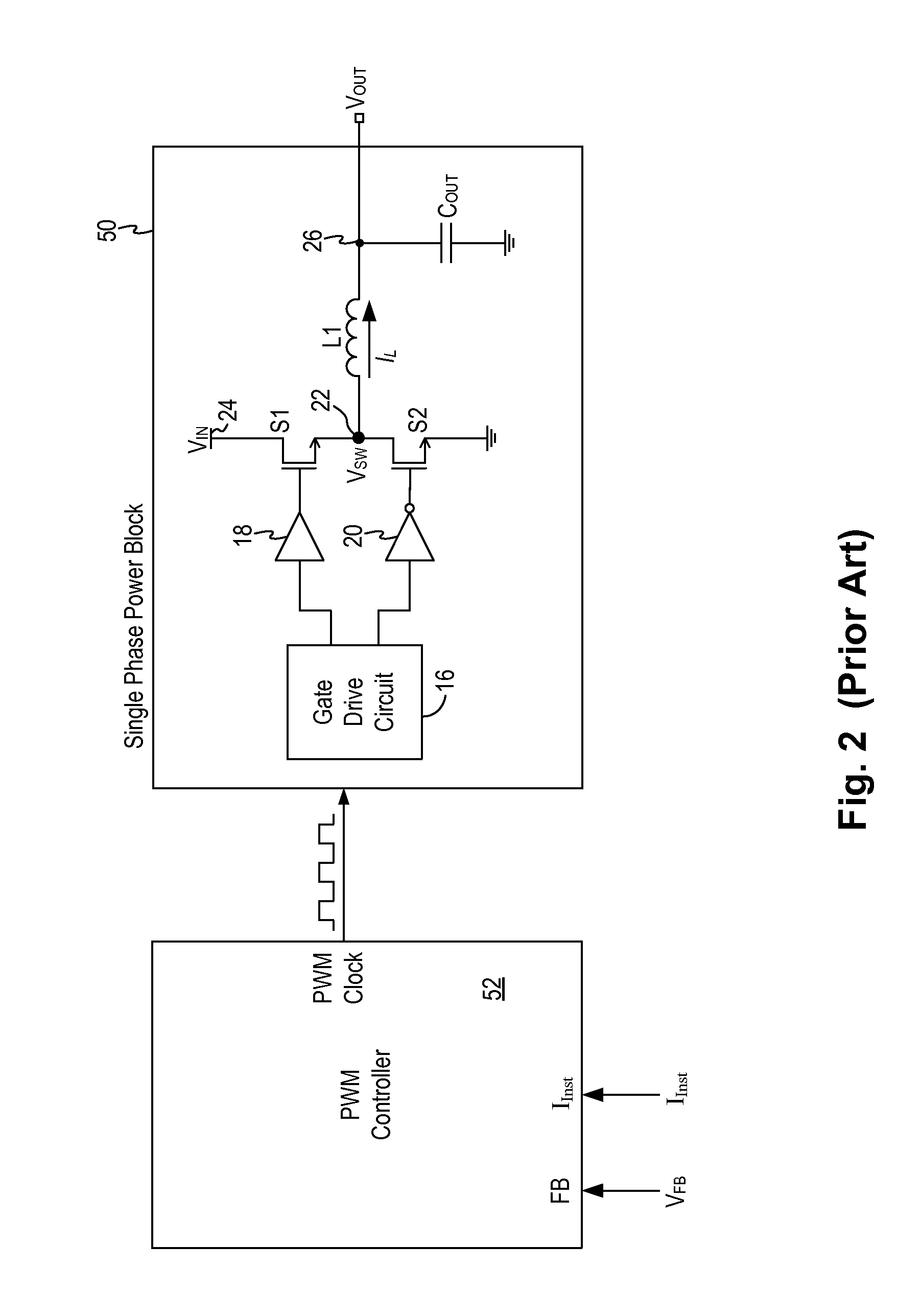
CROSS-REFERENCE TO RELATED APPLICATIONS[0001]This application claims the benefit of U.S. Provisional Patent Application Ser. No. 61 / 530,396, filed on Sep. 1, 2011, and U.S. Provisional Patent Application Ser. No. 61 / 531,567, filed on Sep. 6, 2011, which applications are incorporated herein by reference in their entireties.FIELD OF THE INVENTION[0002]The invention relates to switching regulators and, in particular, to a multi-phase switching regulator power block.DESCRIPTION OF THE RELATED ART[0003]Switch mode power supplies or switching regulators, also referred to as DC to DC converters, are often used to convert an input supply voltage to a desired output voltage at a voltage level appropriate for the internal circuitry of an integrated circuit. For example, a 5 volts supply voltage provided to an integrated circuit may need to be reduced to 2.8 volts on the IC chip to operate the internal circuitry on the chip. A switching regulator provides power supply function through low loss...

Claims


Application Information

Patent Timeline
Patent Type & Authority Applications(United States)
IPC IPC(8): G05F1/46
CPCH02M3/1584H02M2003/1586H02J2001/106H02J1/106H02M3/1586
Inventor KALJE, NITINIZADINIA, MANSOUR
Owner MICREL
Learn More