
LED module fixing strucutre

a technology of led modules and fixing structures, which is applied in the direction of fixed installation, lighting and heating equipment, lighting support devices, etc., can solve the problems of incandescent and fluorescent lamps with the drawbacks of high power consumption, short service life, and low light emission diodes, etc., and achieves simple structure, low cost, and easy installation

Inactive Publication Date: 2013-03-07
RUI TENG OPTO TECH
View PDF7 Cites 32 Cited by
  • Summary
  • Abstract
  • Description
  • Claims
  • Application Information

AI Technical Summary

Benefits of technology

The present invention provides an LED module fixing structure that has a simple thread fixing design that can be easily installed onto another object, reducing manufacturing and installation costs. The LED module is secured onto a heat dissipating element using the threaded column, which allows for enhanced heat dissipating effect. The LED module is secured by a single locking structural design of a screw hole formed at the center of the LED module or lampshade and a threaded column, simplifying the structure, lowering the cost, and facilitating the installation of the LED module.

Problems solved by technology

Conventional illuminating equipments mainly use incandescent and fluorescent lamps as light emitting components, but the incandescent and fluorescent lamps have the drawbacks of high power consumption and short service life.
However, the light emitting diode (LED) still has many technical problems to be solved for its development and penetration in the conventional illumination industry.
For example, it is a technical problem of how to let midstream and upstream manufacturers to manufacture and provide LED modules for simple and easy installations and uses for downstream manufacturers or consumers, such that the LED modules can be applied in road lamps, spot lights or indoor decorative wall lamps and embedded lights.
Such arrangement requires tedious work for the downstream manufacturers or consumers, and a more complicated installation process for the application.

Method used


Image

  • LED module fixing strucutre
  • LED module fixing strucutre
  • LED module fixing strucutre

Examples


Embodiment Construction

[0024]The objects, characteristics and effects of the present invention will become apparent with the detailed description of the preferred embodiments and the illustration of related drawings as follows.

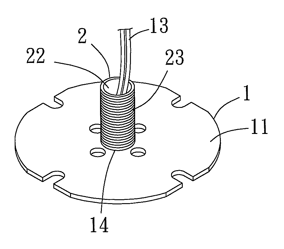
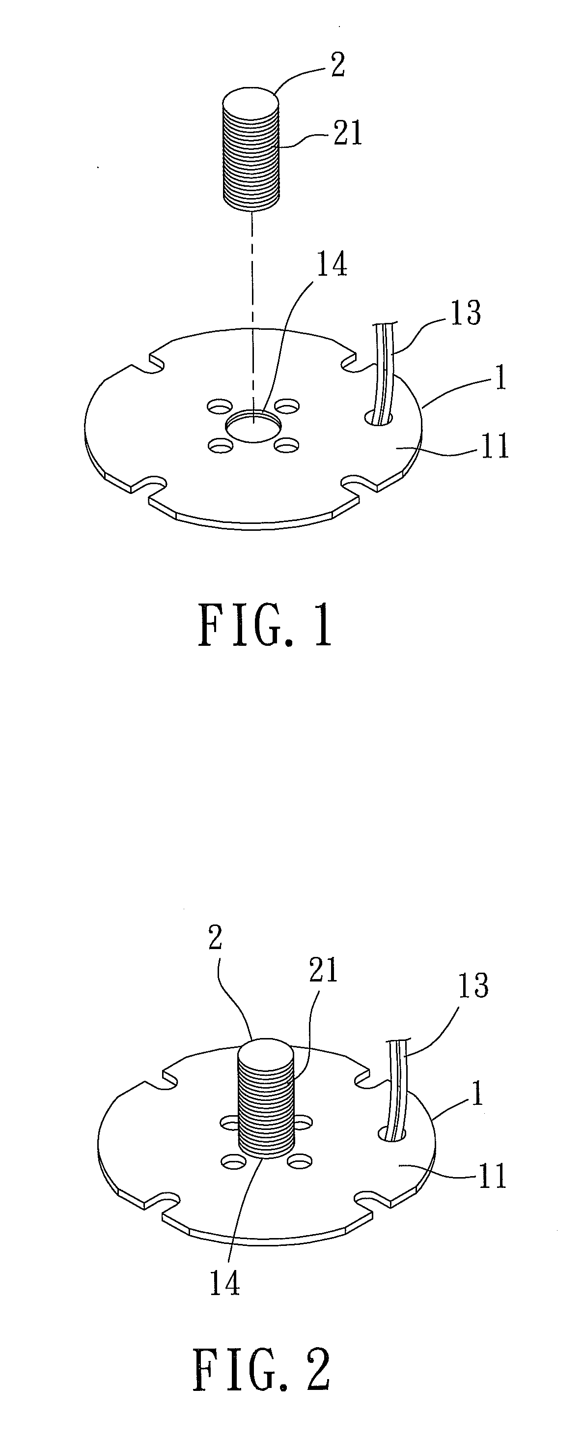
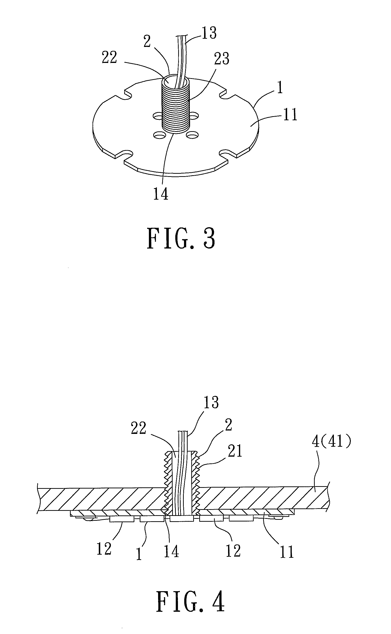
[0025]With reference to FIGS. 1, 2 and 4 for an LED module fixing structure in accordance with a first preferred embodiment of the present invention, the LED module fixing structure comprises an LED module 1 and a threaded column 2, wherein the LED module 1 comprises a circuit substrate 11, one or more LED particles 12 packaged and combined into a surface of the circuit substrate 11a, and an electric wire 13 coupled to the circuit substrate 11, wherein the circuit substrate 11 is made of aluminum or another equivalent material, and a screw hole 14 is formed at the center of the circuit substrate 11. The threaded column 2 is a solid column having a thread 21 formed around the solid column, so that the threaded column 2 can be secured into the screw hole 14 of the circuit substrate 11...


PUM


Abstract

An LED module fixing structure includes an LED module and a threaded column. The LED module includes a circuit substrate, LED particles and an electric wire. A screw hole is formed at the center of the circuit substrate, and a thread is formed around the threaded column, so that the threaded column is secured into the screw hole of the circuit substrate through the thread, or the LED module is installed in a lamp casing, and a screw hole is formed at the center of the lamp casing and provided for securing the threaded column into the screw hole of the lamp casing through the thread. The LED module fixing structure comes with a simple thread fixing structure, and the thread of the threaded column can be installed to another object such as a heat dissipating element to achieve the effects of lowering cost, facilitating installation, and enhancing heat dissipation.

Description

FIELD OF THE INVENTION[0001]The present invention relates to a light emitting diode (LED) module, in particular to the LED module fixing structure.BACKGROUND OF THE INVENTION[0002]Conventional illuminating equipments mainly use incandescent and fluorescent lamps as light emitting components, but the incandescent and fluorescent lamps have the drawbacks of high power consumption and short service life. On the other hand, the present high-power light emitting diode (LED) has the advantages of low power consumption, and durable and long service life, and thus gradually replaces the main trend of the conventional fluorescent lamps. However, the light emitting diode (LED) still has many technical problems to be solved for its development and penetration in the conventional illumination industry. For example, it is a technical problem of how to let midstream and upstream manufacturers to manufacture and provide LED modules for simple and easy installations and uses for downstream manufact...

Claims


Application Information

Patent Timeline
IPC IPC(8): F21V21/00F21V29/00
CPCF21V21/03F21S8/04F21V29/70F21V23/002F21Y2101/02F21V19/0055F21Y2115/10
Inventor CHANG, CHIH-YANG
Owner RUI TENG OPTO TECH
Learn More