Adaptive Driver Delay Compensation

a driver delay and compensation technology, applied in the field of switching power converters, can solve the problems of simple designs and poor power factor, and achieve the effects of accurately controlling peak current, and minimizing error signals

Active Publication Date: 2013-03-07
TEXAS INSTR INC
View PDF6 Cites 16 Cited by
  • Summary
  • Abstract
  • Description
  • Claims
  • Application Information

AI Technical Summary

Benefits of technology

[0005]An embodiment of the present invention provides a method for accurately controlling peak current in a switching regulator. An error signal is formed that is indicative of an amount of time the load current exceeds a peak current reference value. A reference value is dynamically adjusted to minimize the error signal and thereby accurately control peak current.

Problems solved by technology

However, they are more complicated, their switching currents can cause electrical noise problems if not carefully suppressed, and simple designs may have a poor power factor.

Method used


Image

  • Adaptive Driver Delay Compensation
  • Adaptive Driver Delay Compensation
  • Adaptive Driver Delay Compensation

Examples


Embodiment Construction

[0019]Specific embodiments of the invention will now be described in detail with reference to the accompanying figures. Like elements in the various figures are denoted by like reference numerals for consistency. In the following detailed description of embodiments of the invention, numerous specific details are set forth in order to provide a more thorough understanding of the invention. However, it will be apparent to one of ordinary skill in the art that the invention may be practiced without these specific details. In other instances, well-known features have not been described in detail to avoid unnecessarily complicating the description.

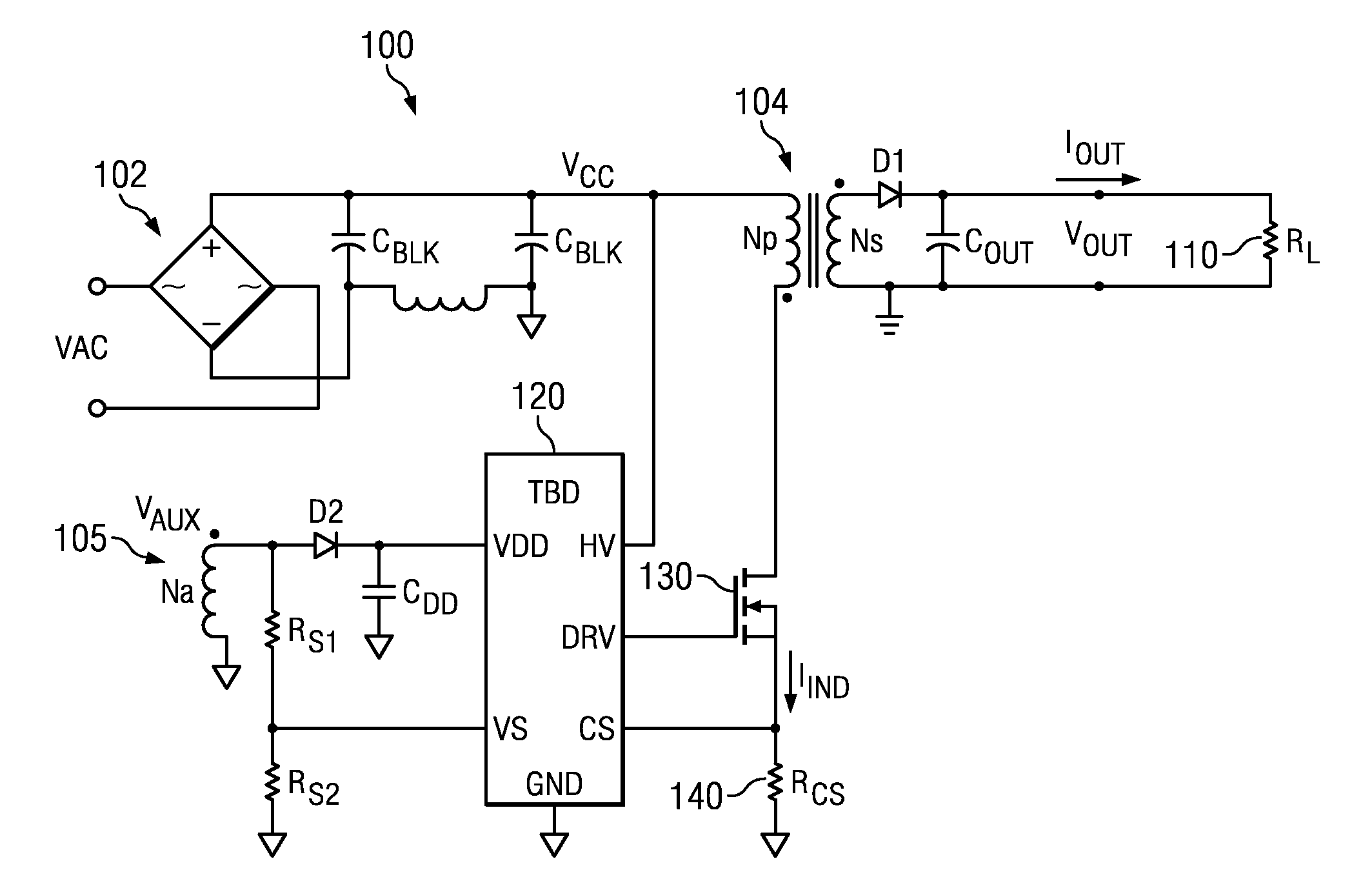
[0020]In some applications, there is a need to monitor a parameter and to accurately control the parameter. For example, it may be desirable to change the output state of a driver from “on” to “off” when the parameter reaches the desired trip point. In the real word, when the desired trip point is reached, there will be a time delay (Td) to cha...


PUM


Abstract

Peak current in a switching converter is controlled using a closed loop to compensate for error caused by delay time in the switching transistor and control logic. A reference value is established that represents a target current value. A compensated reference value is derived from the reference value by the closed loop. A periodic inductor current is formed in the switching converter in response to the compensated reference value. An error signal is formed that is indicative of an amount of time the inductor current exceeds the target current value. The compensated reference value is dynamically adjusted by the compensation closed loop to minimize the error signal.

Description

FIELD OF THE INVENTION[0001]This invention generally relates to switching power converters, and in particular to accurately limiting peak current in a switching power converter.BACKGROUND OF THE INVENTION[0002]A switched-mode power supply (SMPS), also referred to simply as a switcher, is an electronic power supply that incorporates a switching regulator in order to be highly efficient in the conversion of electrical power. Like other types of power supplies, an SMPS transfers power from a source like the electrical power grid to a load while converting voltage and current characteristics. An SMPS is usually employed to efficiently provide a regulated output voltage, typically at a level different from the input voltage. Unlike a linear power supply, the pass transistor of a switching mode supply switches very quickly (typically between 50 kHz and 1 MHz) between full-on and full-off states, which minimizes wasted energy. Voltage regulation is provided by varying the ratio of on to of...

Claims


Application Information

Patent Timeline
Patent Type & Authority Applications(United States)
IPC IPC(8): H02M3/335
CPCH02M2001/0025H02M3/33507H02M1/0025
Inventor MARINO, FILIPPO
Owner TEXAS INSTR INC
Why Eureka
Try Eureka