
Flight Control Laws for Vertical Flight Path

a flight control and vertical flight technology, applied in the field of flight control systems, can solve the problems of misjudging the vertical flight path, pilots might accidentally fly into an external hazard, and maximum actuation rates must be limited,

Active Publication Date: 2013-03-07
TEXTRON INNOVATIONS
View PDF11 Cites 34 Cited by
  • Summary
  • Abstract
  • Description
  • Claims
  • Application Information

AI Technical Summary

Benefits of technology

The present invention relates to flight control systems for rotorcraft, particularly those that enable precise control of a vertical flight path. The technical effects of the invention include reducing pilot workload during ground-referenced maneuvering, improving maneuvering in confined spaces, and enabling fast, full authority control of rotor collective pitch. The invention also eliminates the need for trimming cockpit controls and simplifies the cockpit controls design by allowing for a unique trim design.

Problems solved by technology

In addition to needing to transition into and out of hover, these aircraft can spend significant portions of their mission maneuvering at low speeds relative to the ground.
With the lack of visual cues to detect off-axis motion, the pilot might accidentally fly into an external hazard while maneuvering in a confined space.
In degraded visual environments, including inadvertent entry into brown out or white out conditions, misjudging vertical flight path could have catastrophic results.
First, since an actuator failure might result in a runaway collective controller, the maximum actuation rates must be limited.
With this rate limiting, the collective might not be able to move fast enough to maintain the vertical parameter during maneuvering flight.
For example, during an aborted takeoff, the initial pitch up to slow down will result in altitude ballooning since the parallel trim actuator cannot move the collective down fast enough to hold altitude.
As the aircraft slows down to a hover, the trim actuator cannot move the collective up fast enough to keep it from sinking into the ground.
Another drawback of using a parallel trim actuator for vertical control is the increased pilot workload to change the vertical state.
This increase in workload could degrade vertical flight path precision during GRM.
The last drawback of the parallel trim actuator is that once the pilot has overridden it with either force or a FTR switch, the feedback control system is disabled and all of the advantages of control augmentation are lost.
With high redundancy in the control system components, the probability of a control system failure is low enough to enable fast, full authority control of rotor collective pitch, or any other control surfaces used for vertical control of the aircraft.
The main drawback of using a unique trim controller in the vertical axis is that the pilot has no tactile feedback on actual collective position or aircraft power.
This distraction could result in a loss of situational awareness during critical phases of a flight, like GRM or while handling emergency procedures such as a loss of power.

Method used


Image

  • Flight Control Laws for Vertical Flight Path
  • Flight Control Laws for Vertical Flight Path
  • Flight Control Laws for Vertical Flight Path

Examples


Embodiment Construction

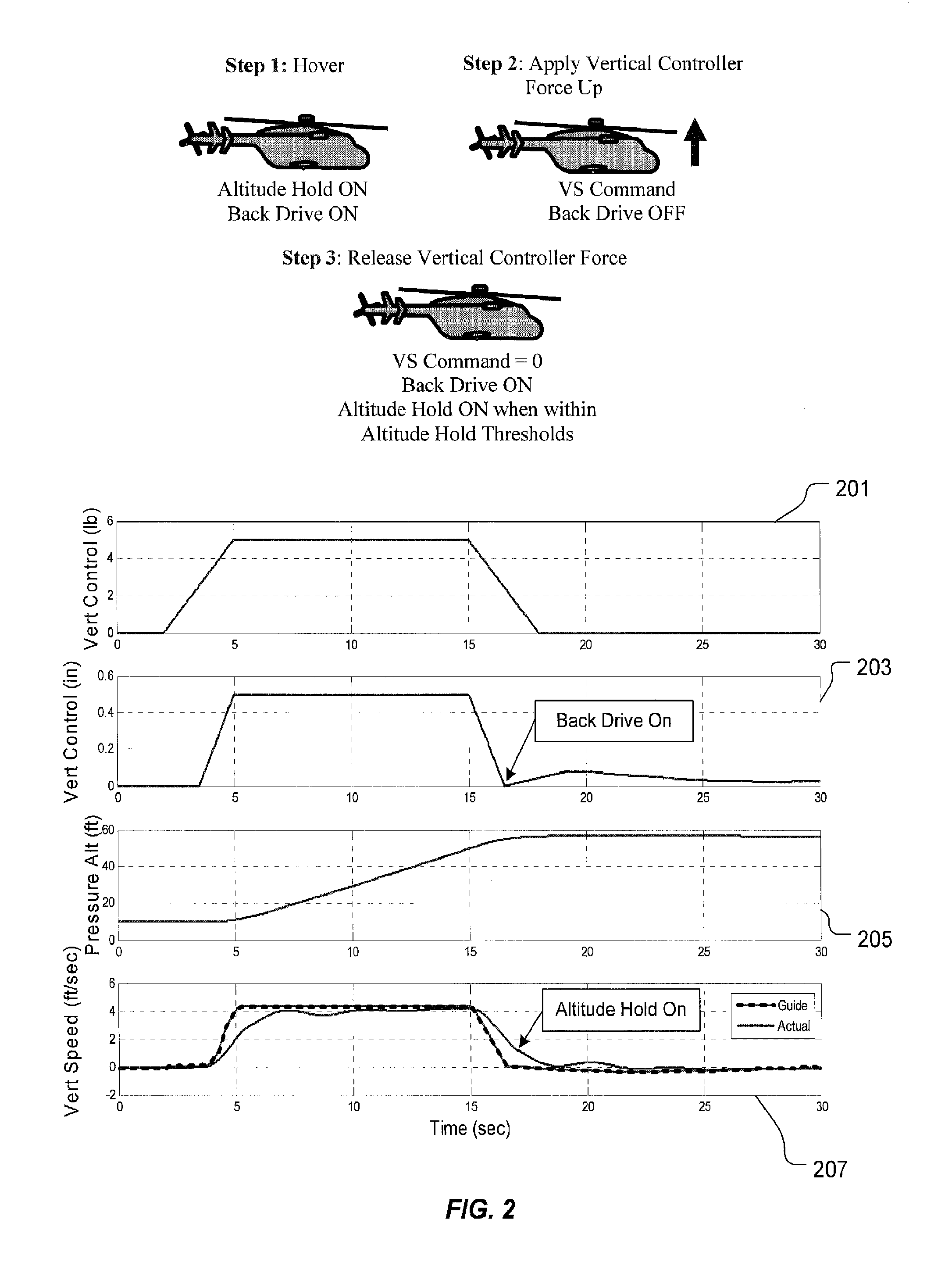
[0031]The flight control laws enable precise vertical flight path control (VFPC) throughout the flight envelope, while providing tactile feedback to the pilot on aircraft power state. In the absence of vertical control inputs by the pilot, the control laws will hold either altitude or VFPA. Vertical beep inputs enable precise changes to either altitude or VFPA. During vertical hold and beep operations, the cockpit vertical controller will be back driven to approximately match the actual vertical command being sent to the aircraft's vertical controls (main rotor collective pitch for helicopters). Pilot inputs into the vertical controller will command changes in VS.

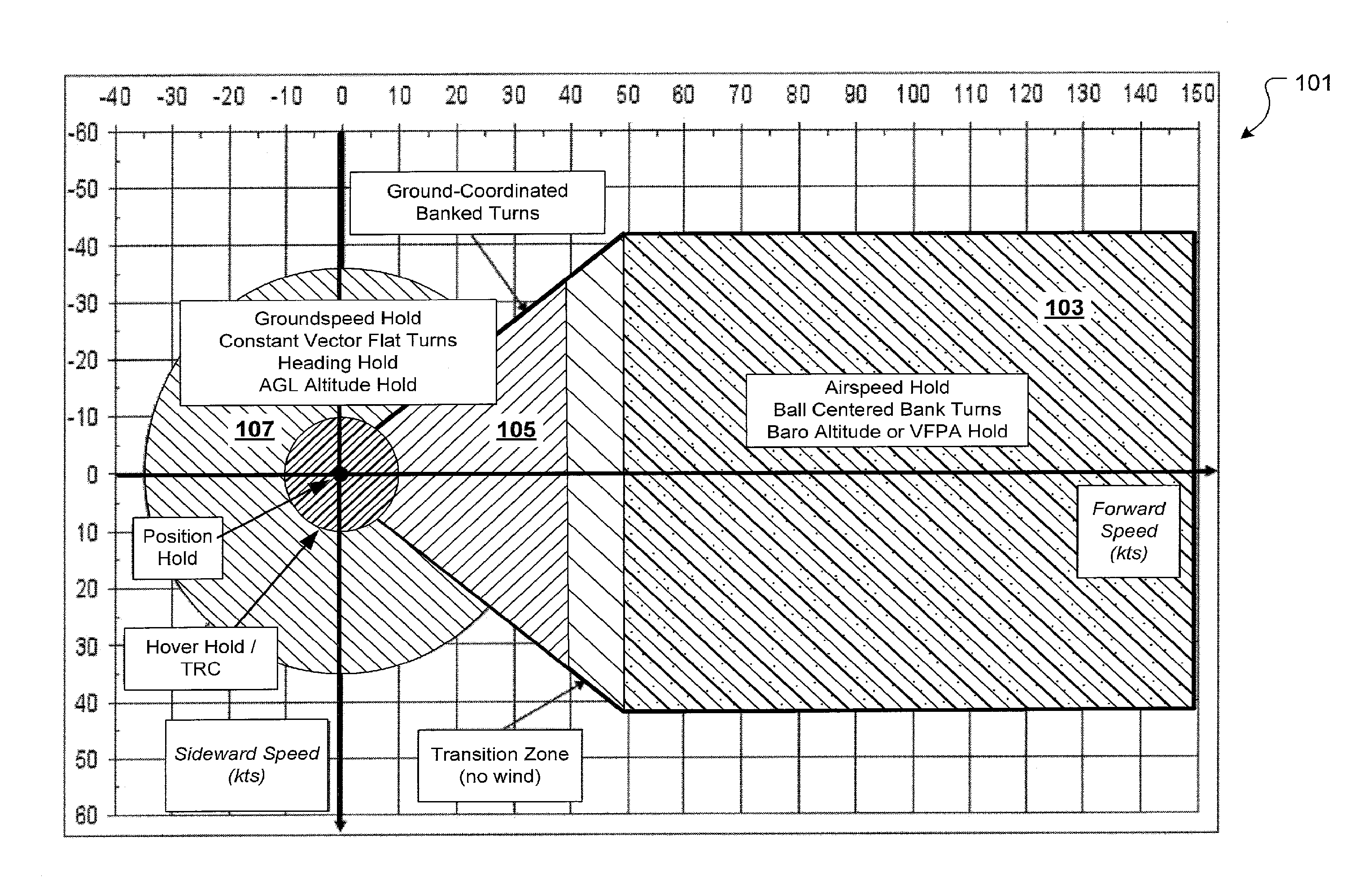
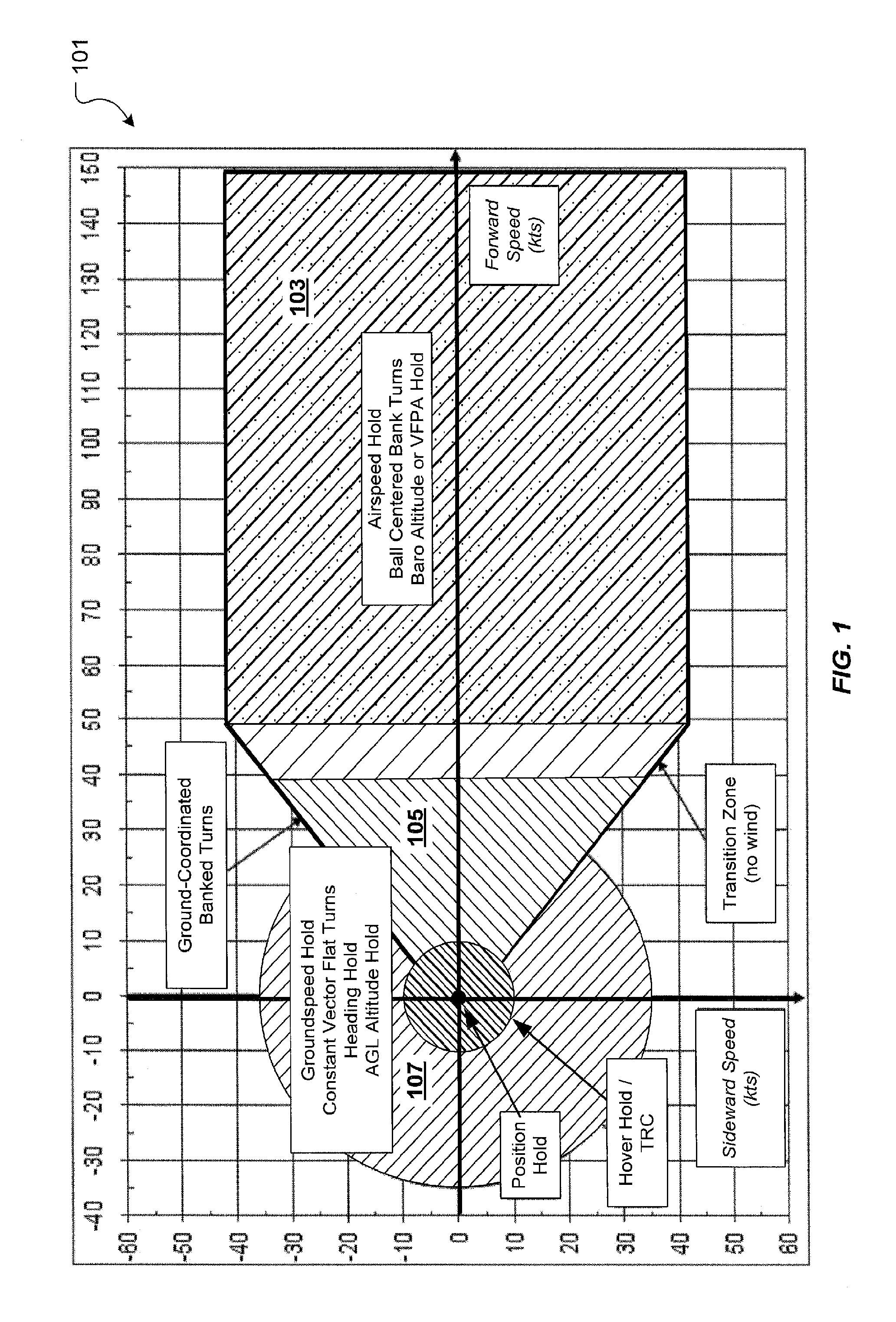
[0032]FIG. 1 shows a representative flight envelope 101 with the control law modes designed to enable GRM. For this invention, region 103 depicts the higher speed VFPC envelope, while region 105 and region 107 depict the low speed VFPC envelope. At higher speed, VFPC will hold either barometric altitude or VFPA. With the in...


PUM


Abstract

A flight control system and method for controlling the vertical flight path of an aircraft, the flight control system includes a stable decoupled model having a decoupled lateral equation of motion and a decoupled longitudinal equation of motion and a feedback command loop operably associated with the stable decoupled model. The feedback command loop includes a vertical flight path angle control law; an altitude control law; and a vertical speed control law.

Description

TECHNICAL FIELD[0001]The present invention relates generally to flight control systems, and more particularly, to flight control laws which enable precise control of a vertical flight path.DESCRIPTION OF THE PRIOR ART[0002]Aircraft which can hover and fly at low speeds include rotorcraft, such as helicopters and tilt rotors, and jump jets, i.e., the AV-8B Harrier and F-35B Lightning II. In addition to needing to transition into and out of hover, these aircraft can spend significant portions of their mission maneuvering at low speeds relative to the ground. Sometimes, this maneuvering must be conducted in confined spaces around external hazards such as buildings, trees, towers, and power lines.[0003]For traditional flight control systems, ground-referenced maneuvering (GRM) requires the pilot to make constant control inputs in multiple axes in order to counter disturbances caused by wind, as well as to remove the natural coupled response of the aircraft. The pilot workload during suc...

Claims


Application Information

Patent Timeline
IPC IPC(8): B64C19/00
CPCG05D1/102G05D1/0858G05D1/0607
Inventor CHRISTENSEN, KEVIN THOMASSHUE, SHYHPYNG JACKCAUDILL, TROY SHELDON
Owner TEXTRON INNOVATIONS
Learn More