Running-resistance control device

a control device and chassis technology, applied in the direction of instruments, structural/machine measurement, liquid/fluent solid measurement, etc., can solve the problem of influencing the running resistance obtained on the actual road

Inactive Publication Date: 2013-03-07
MEIDENSHA ELECTRIC MFG CO LTD
View PDF2 Cites 17 Cited by
  • Summary
  • Abstract
  • Description
  • Claims
  • Application Information

AI Technical Summary

Benefits of technology

[0012]FIG. 2 A configuration view of a running-resistance control device according to the present invention.

Problems solved by technology

However, the running resistance obtained on the actual road is influenced by its environment, particularly by air pressure.

Method used


Image

  • Running-resistance control device
  • Running-resistance control device
  • Running-resistance control device

Examples


Embodiment Construction

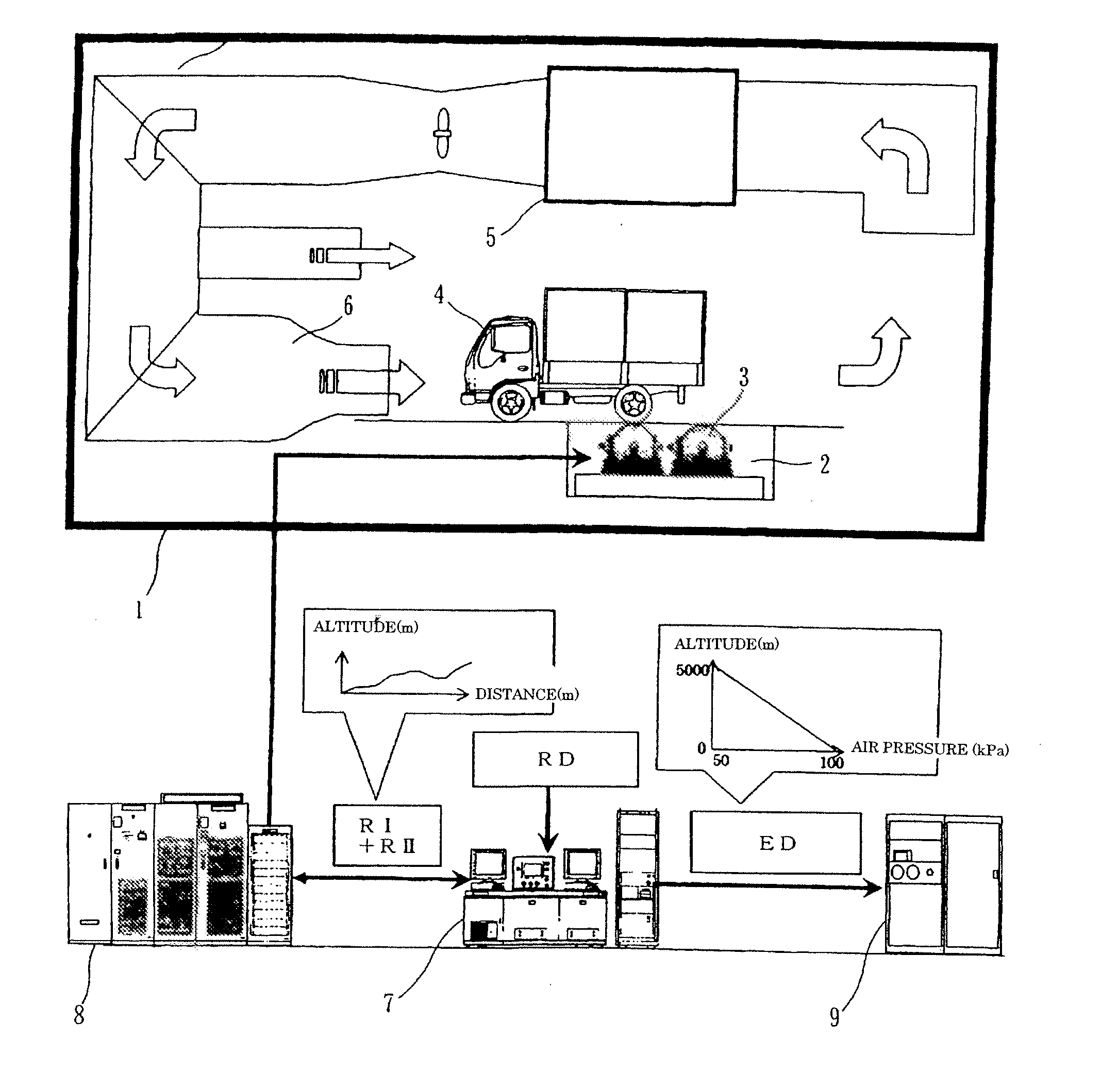
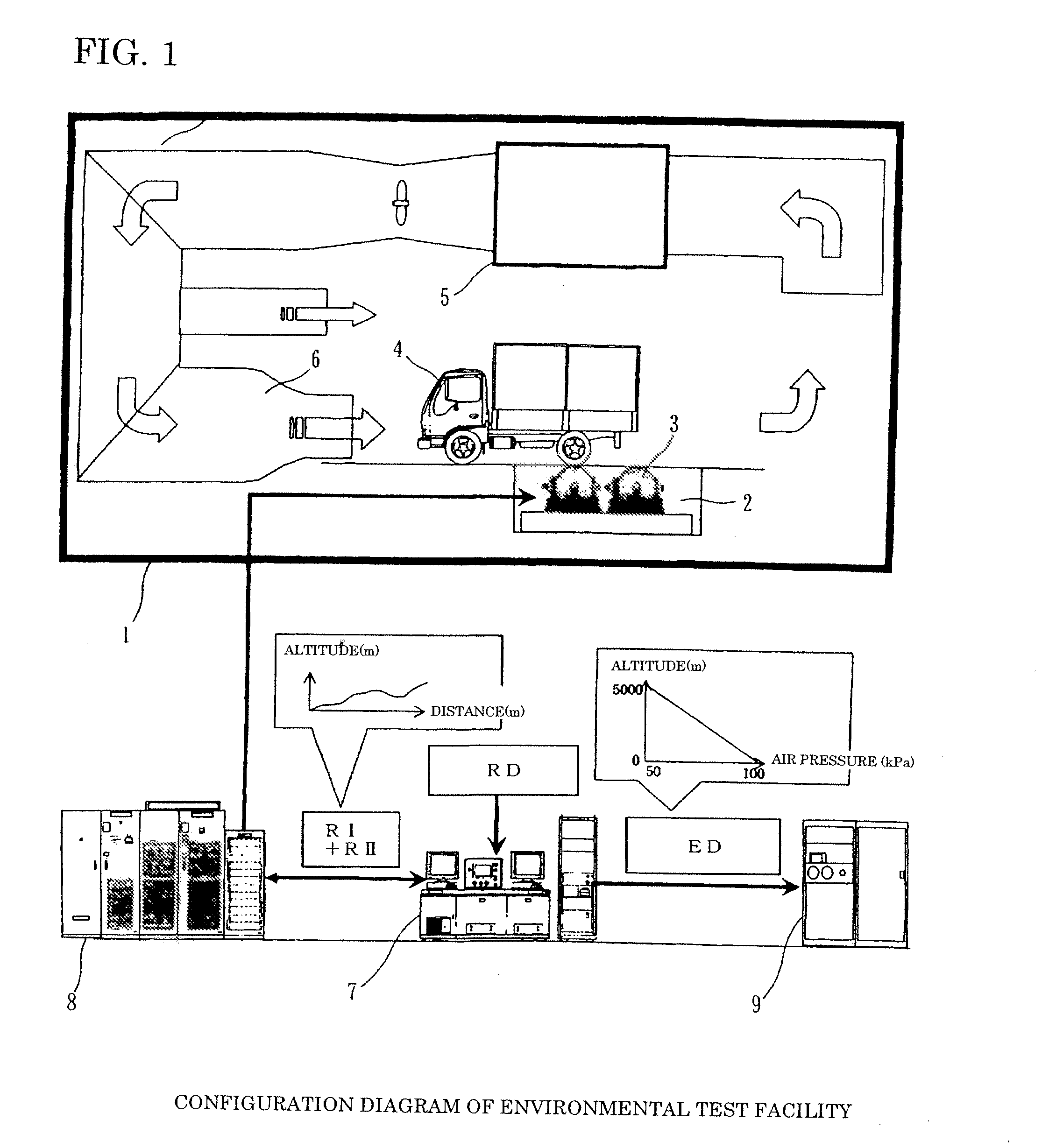
[0013]FIG. 1 is a schematic configuration view of chassis dynamometer system showing an embodiment according to the present invention. A reference sign 1 denotes an environmental test laboratory. A reference sign 2 denotes a dynamometer. A reference sign 3 denotes a roller(s) on which a drive wheel(s) of a vehicle 4 under test is placed or held. A reference sign 5 denotes an air-conditioning equipment. The air-conditioning equipment 5 controls air temperature and air pressure in the environmental laboratory, and blows wind (corresponding to air resistance) to a front of the under-test vehicle 4 through a wind tunnel 6. A reference sign 7 denotes an operation panel for the chassis dynamometer. The operation panel 7 is constituted by a personal computer and the like. The operation panel 7 sets a real-road data (actual-road data) RD such as vehicle speed, distance and altitude, and sets a running resistance-and-inclination (gradient) command RI and an environmental simulation command E...


PUM

PropertyMeasurementUnit
pressureaaaaaaaaaa
temperatureaaaaaaaaaa
running resistanceaaaaaaaaaa

Abstract

At a highland, a composition rate of air resistance is low which is included in a running resistance, because air density is low. This influences a vehicle running. Hence, a high-altitude environmental test for a vehicle by use of chassis dynamometer produces a result different from that of actual-road running. Therefore, an environmental-correction calculating section is provided on an input side of a running-resistance-command generating section configured to generate a running-resistance command. The environmental-correction calculating section receives an air temperature signal and an air pressure signal which are detected inside an environmental test laboratory, calculates an environmental correction value of rolling resistance and an environmental correction value of air resistance, and calculates a target running resistance from the environmental correction values. The running-resistance-command generating section controls the chassis dynamometer by generating the running-resistance command based on the target running resistance and a speed detection signal of the chassis dynamometer.

Description

TECHNICAL FIELD[0001]The present invention relates to a running-resistance control device for a chassis dynamometer, particularly to a running-resistance control device adapted to respond to an environmental change in a test laboratory.BACKGROUND ART[0002]Instead of conducting an evaluation test by driving a (assembly-)finished vehicle on a road, recently, a drive wheel(s) of the finished vehicle is placed on a roller of chassis dynamometer for evaluation. In such a case, a running-resistance load which is generated by the road running of the vehicle is simulated by setting an absorption load torque of the chassis dynamometer. At this case, a running resistance has been obtained by causing the vehicle to coast on an actual road such as a test course in advance. When such a running-resistance data is obtained, the environment such as wind velocity, air temperature, air pressure and humidity takes a wide range of variations. Hence, the obtained data is treated as a data under a standa...

Claims


Application Information

Patent Timeline
Patent Type & Authority Applications(United States)
IPC IPC(8): G01L3/00G06F19/00
CPCG01M17/0074G01M17/007
Inventor NARUMI, YASUMASA
Owner MEIDENSHA ELECTRIC MFG CO LTD
Why Eureka
Try Eureka