Computer System and Method for Comparing Output Signals

Active Publication Date: 2013-03-07
HENSOLDT SENSORS GMBH
View PDF5 Cites 21 Cited by
  • Summary
  • Abstract
  • Description
  • Claims
  • Application Information

AI Technical Summary

Benefits of technology

[0003]Exemplary embodiments of the present invention are directed to a computer system, a method and a computer program that overcome the aforementi

Problems solved by technology

However, a drawback of this is that such test procedures are time consuming and expensive.
Sim

Method used


Image

  • Computer System and Method for Comparing Output Signals
  • Computer System and Method for Comparing Output Signals
  • Computer System and Method for Comparing Output Signals

Examples


Embodiment Construction

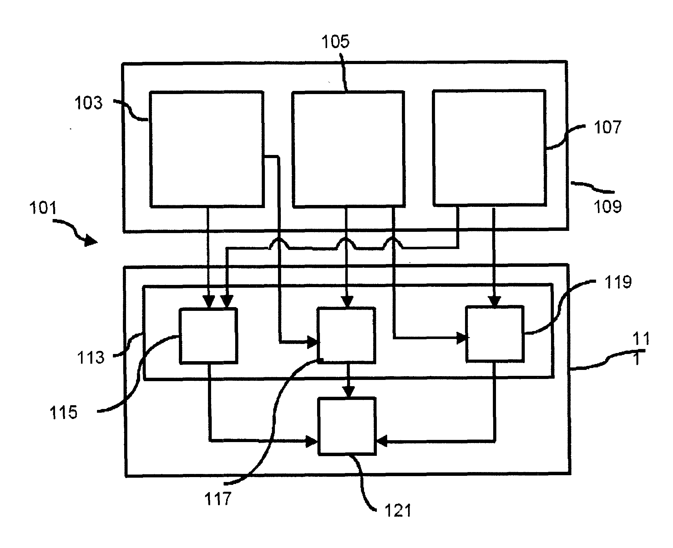
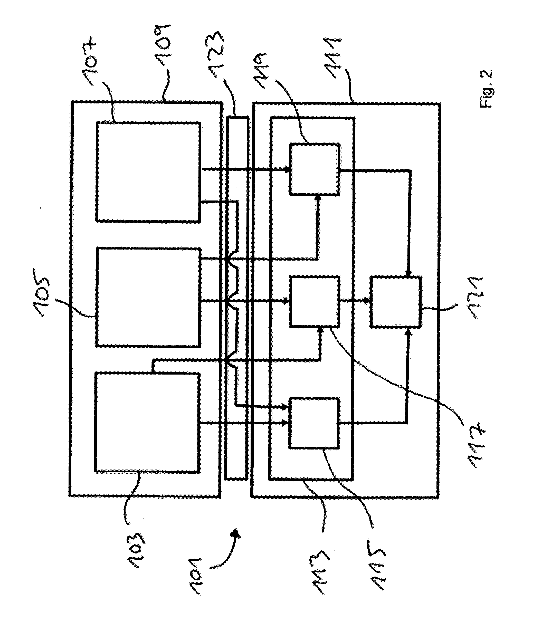
[0042]FIG. 1 shows a computer system 101 with three COTS processor cores 103, 105 and 107, which are preferably not of the same design. The three COTS processor cores 103, 105 and 107 are integrated in a processor 109. The processor 109 is thus a three-core processor. In an exemplary embodiment that is not shown, the processor 109 may be a four-core, eight-core or sixteen-core processor. In a further exemplary embodiment that is not shown, the three COTS processor cores 103, 105 and 107 are each integrated in a separate processor.

[0043]The computer system 101 also comprises a logic circuit device 111 in which an evaluation device 13 is integrated. The evaluation device 113 comprises three comparison means 115, 117 and 119. The comparison means 115 is connected to the COTS processor 103 and 107, and receives the respective output signals from the COTS processor cores 103 and 107. The comparison means 117 is connected to the COTS processor cores 103 and 105 and receives the respective...


PUM


Abstract

A computer system includes at least two COTS processor cores and an evaluating device connected to the at least two COTS processor cores for evaluating output signals output by means of the at least two COTS processor cores. The evaluating device includes a comparator for pair-wise comparison of the respective generated output signals with each other. The comparator also outputs a comparison signal corresponding to the respective comparison of the output signals.

Description

[0001]The invention relates to a computer system and a method for comparing output signals that are output by means of at least two COTS processor cores. The invention also relates to a computer program.BACKGROUND OF THE INVENTION[0002]Computer systems used in safety-critical fields such as the aerospace industry, need to undergo various standardized test procedures, some of which are regulated by legislation. Such test procedures or standards comprise SAE ARP4754, SAE ARP4761, RTCA DO-178b or RTCA DO-254, in particular. Such safety-critical computer systems have, in particular, certified hardware components, such as circuits, manufactured specifically for the respective application, particularly application-specific integrated circuits (ASIC), processors or processor cores. In this context, particularly the RTCA DO-178b / ED-12B and the RTCA DO-254 / ED-80 development and test procedures, subsequently called test procedures for short, demand a particularly intensive check on the design...

Claims


Application Information

Patent Timeline
IPC IPC(8): G06F11/30
CPCG06F11/1641G06F11/188G06F11/184
Inventor GEIGER, DIETMARPAULITSCH, MICHAEL
Owner HENSOLDT SENSORS GMBH
Why Eureka
Try Eureka