Intake manifold of comburent air for an internal combustion engine equipped with egr

a technology of comburent air and internal combustion engine, which is applied in the direction of air intake for fuel, exhaust gas recirculation, and addition of non-fuel substances to fuel, etc., can solve the problems of reduced nitrogen oxide production (nox) during the combustion process, non-homogeneous combustion among the various cylinders, and unsatisfactory efficiency of the whole recirculating system. , to achieve the effect of reducing load loss

Active Publication Date: 2013-03-14
LOMBARDINI SRL
View PDF8 Cites 13 Cited by
  • Summary
  • Abstract
  • Description
  • Claims
  • Application Information

AI Technical Summary

Benefits of technology

[0018]In a still further aspect of the invention, the intake manifold comprises deflector means associated with the wall at the position of opening, for reducing the load loss of the gases crossing the opening as they pass from the first chamber to the second chamber.
[0019]Thanks to this detail, the passage of the gas mixture through the opening of the wall results in a limited load loss and gases are conveyed into the second chamber towards the outlet thereof.

Problems solved by technology

In this way, a fraction of exhaust gas is mixed with the fresh air in inlet and the mixture supplies the engine cylinders, thus reducing the production of nitrogen oxides (NOx) during the combustion process.
The EGR systems of known type, however, are not free of drawbacks, among which is the fact that the fresh air and the exhaust gases in inlet into the intake manifold, are not always sufficiently mixed with one another, so that the distribution of the exhaust gas among the engine cylinders is not always optimal, and gives rise to a non-homogeneous combustion among the various cylinders, which makes the whole recirculating system not particularly efficient.

Method used


Image

  • Intake manifold of comburent air for an internal combustion engine equipped with egr
  • Intake manifold of comburent air for an internal combustion engine equipped with egr
  • Intake manifold of comburent air for an internal combustion engine equipped with egr

Examples


Embodiment Construction

[0030]With particular reference to the figures of the drawings, an internal combustion engine is denoted in its entirety by reference numeral 51, in this case a Diesel motor.

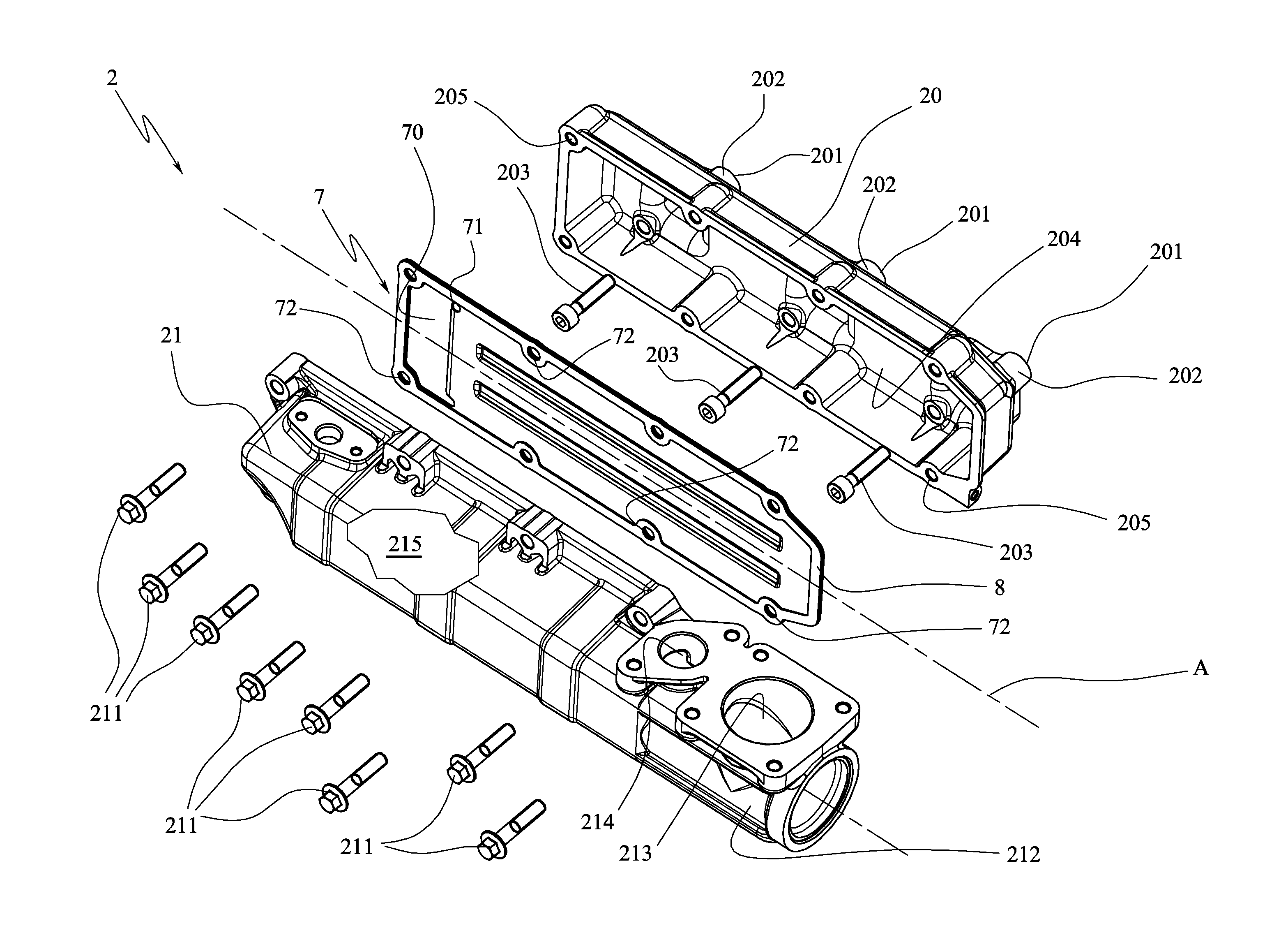
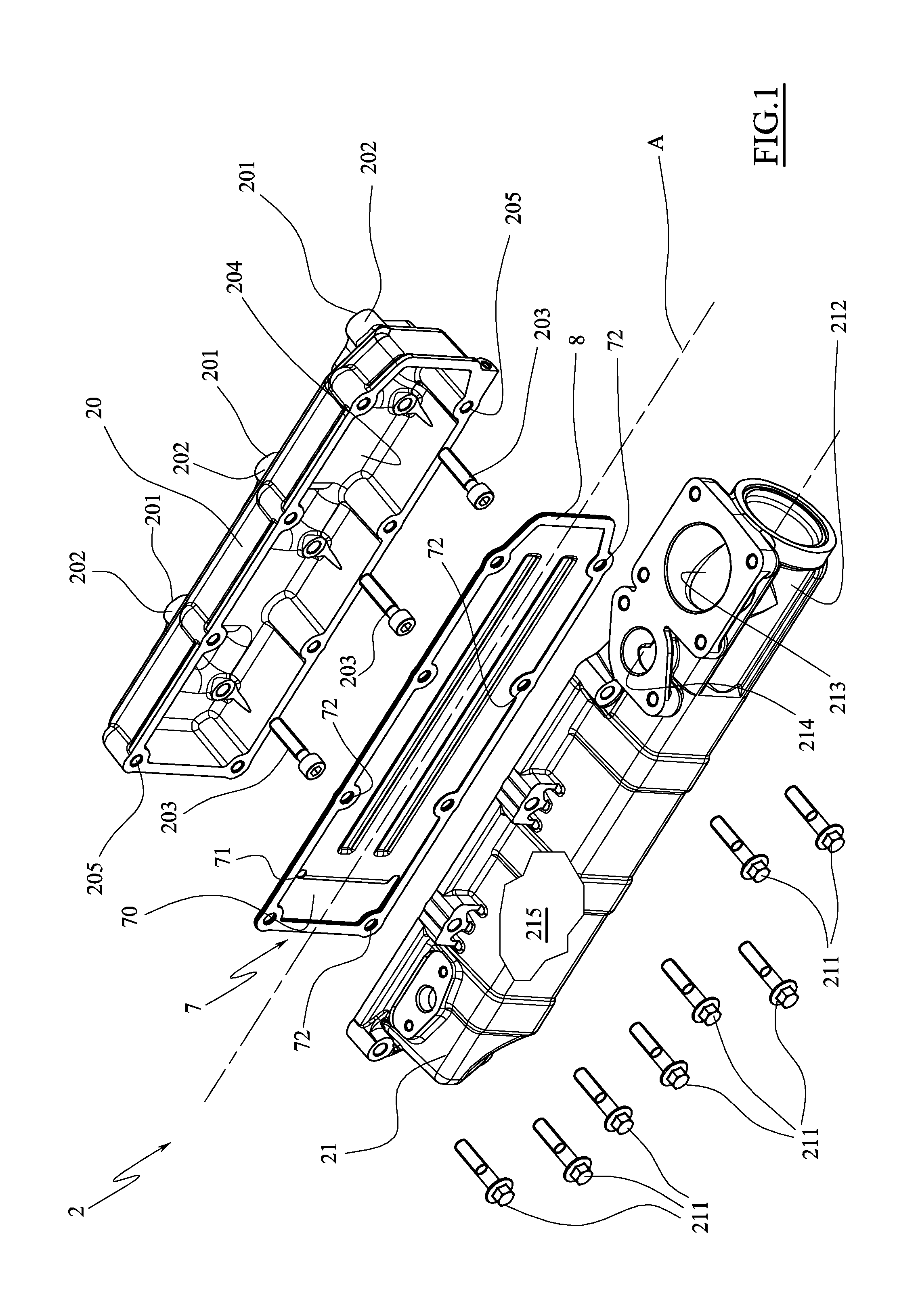
[0031]The internal combustion engine 1 has an intake manifold 2 and an exhaust manifold 3.

[0032]The intake manifold 2 is connected to an intake line 4 for transporting fresh air from the environment into the internal combustion engine 1, while the exhaust manifold 3 is conventionally connected to an exhaust line 5 such as to convey the exhaust gases from the internal combustion engine 1 into the environment.

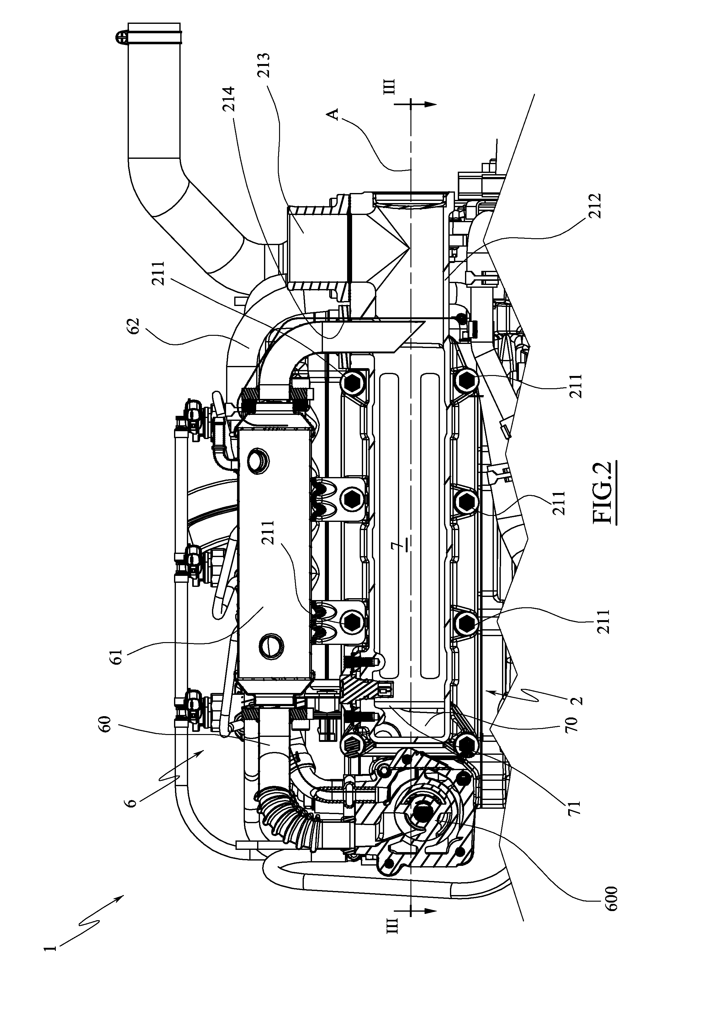
[0033]The internal combustion engine 1 is equipped with an exhaust gas recirculation system (EGR), denoted in its entirety by 6, which is provided for recycling and supply of the exhaust gases into the internal combustion engine 1 in order to reduce emissions of nitrogen oxides (NOx).

[0034]The EGR system 6 comprises a recirculation conduit 60 which connects the exhaust manifold 3 directly to the intake manifo...


PUM


Abstract

An intake manifold (2) of comburent air is provided for an internal combustion engine (1) with a recirculating conduit (60) of exhaust gases. The intake manifold (2) includes a first inlet mouth (213) of the comburent air, a second inlet mouth (214) in communication with the recirculating conduit (60) of the exhaust gases, and a plurality of outlet mouths (201), having a wall (7) positioned in front of each of the outlet mouths (201) and suitable for dividing the internal volume of the intake manifold (2) into two chambers (215, 204), the first chamber (215) being placed in communication with the first inlet mouth (213) and the second inlet mouth (214) and the second chamber (204) being placed in communication with the outlet mouths (201), the wall (7) defining an opening (70) suitable for placing the first chamber (215) and the second chamber (204) in communication.

Description

TECHNICAL FIELD [0001]The present invention relates to an intake manifold of comburent air for an internal combustion engine, usually an internal combustion engine of vehicles, which is provided with an exhaust gas recirculation system.PRIOR ART [0002]As is known, an internal combustion engine is conventionally provided with an intake manifold, an exhaust manifold, an intake line for conveying fresh air from the environment into the intake manifold, and an exhaust line for conveying the exhaust gas from the exhaust manifold to the environment. With the aim of reducing the polluting emissions, the majority of internal combustion engines, especially Diesel engines, are further provided with a recirculating system of the exhaust gases (EGR), selectively activatable for recirculating a part of the exhaust gases from the exhaust manifold in the intake manifold.[0003]In this way, a fraction of exhaust gas is mixed with the fresh air in inlet and the mixture supplies the engine cylinders, ...

Claims


Application Information

Patent Timeline
Patent Type & Authority Applications(United States)
IPC IPC(8): F02M35/104
CPCY02T10/121F02M35/10262F02M35/10222F02M25/0728F02M25/0735Y02T10/146F02M35/1045F02M35/10354F02M26/25F02M26/30Y02T10/12
Inventor BORGHI, GIANNI
Owner LOMBARDINI SRL
Why Eureka
Try Eureka