Device and method for controlling energy

a technology of electromagnetic energy and control device, which is applied in the direction of manufacturing tools, electrical/magnetic/electromagnetic heating, sustainable buildings, etc., can solve the problems of lack of uniform heating, hot spots and cold spots

Active Publication Date: 2013-03-14
JOLIET 2010 LTD
View PDF21 Cites 59 Cited by
  • Summary
  • Abstract
  • Description
  • Claims
  • Application Information

AI Technical Summary

Benefits of technology

[0017]Irradiating the load may be controlled for limiting the overall durations during which individual frequencies are tr...

Problems solved by technology

Among the many problems associated with known MW ovens is a lack of uniformity in heating, ...

Method used


Image

  • Device and method for controlling energy
  • Device and method for controlling energy
  • Device and method for controlling energy

Examples


Embodiment Construction

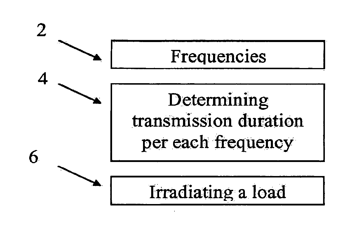
[0065]The present embodiments comprise an apparatus and a method for controlling the amount of EM energy that dissipates into a load at each transmitted modulation space element (MSE; as will be described below in detail) and in particular, to such a controlling through modulation of the period in which each MSE is transmitted, particularly within a duty cycle of the MSEs. The dissipation of energy may be used, for example, for any form of heating utilizing irradiation of energy, at times without a temperature increase, including one or more of thawing, defrosting, warming, cooking, drying etc. The term “electromagnetic energy” or “EM energy”, as used herein, includes any or all portions of the electromagnetic spectrum, including but not limited to, radio frequency (RF), infrared (IR), near infrared, visible light, ultraviolet, etc. In one particular example, applied electromagnetic energy may include RF energy with a wavelength in free space of 100 km to 1 mm, which is a frequency ...


PUM

PropertyMeasurementUnit
Timeaaaaaaaaaa
Poweraaaaaaaaaa
Ratioaaaaaaaaaa

Abstract

Apparatuses and methods for applying EM energy to a load. The apparatuses and methods may include at least one processor configured to receive information indicative of energy dissipated by the load for each of a plurality of modulation space elements. The processor may also be configured to associate each of the plurality of modulation space elements with a corresponding time duration of power application, based on the received information. The processor may be further configured to regulate energy applied to the load such that for each of the plurality of modulation space elements, power is applied to the load at the corresponding time duration of power application.

Description

RELATED APPLICATIONS[0001]This application claims the benefit of 1) International Application No. PCT / IL 2009 / 001057 entitled “Device and Method For Controlling Energy,” filed on Nov. 10, 2009; 2) U.S. Provisional Patent Application entitled “Modal Analysis,” filed on May 3, 2010; 3) U.S. Provisional Patent Application entitled “Loss Profile Analysis,” filed on May 3, 2010; and 4) U.S. Provisional Patent Application entitled “Spatially Controlled Energy Delivery,” filed on May 3, 2010. All of these listed applications are fully incorporated herein by reference in their entirety.[0002]The present application is related to four other U.S. Provisional Patent applications filed on May 3, 2010, entitled: 1) Modal Energy Application; 2) Degenerate Modal Cavity; 3) Partitioned Cavity; and 4) Antenna Placement in an Electromagnetic Energy Transfer System. All of these listed applications are fully incorporated herein by reference in their entirety.FIELD OF THE INVENTION[0003]The present app...

Claims


Application Information

Patent Timeline
IPC IPC(8): B23K13/08
CPCH05B6/705H05B2206/044H05B1/02Y02B40/143Y02B40/146H05B6/688H05B6/72H05B6/00H05B6/686H05B6/70Y02B40/00H05B6/68H05B6/6447H05B6/6455H05B6/687
Inventor BILCHINSKY, ALEXANDERBEN-SHMUEL, ERANEINZINGER, PINCHASRAPPEL, AMIT
Owner JOLIET 2010 LTD
Why Eureka
Try Eureka