

Tire vulcanizing method, and tire vulcanizer
- Summary
- Abstract
- Description
- Claims
- Application Information
AI Technical Summary
Benefits of technology
Problems solved by technology
Method used
Image

Examples
experiment condition
(Experiment Condition)
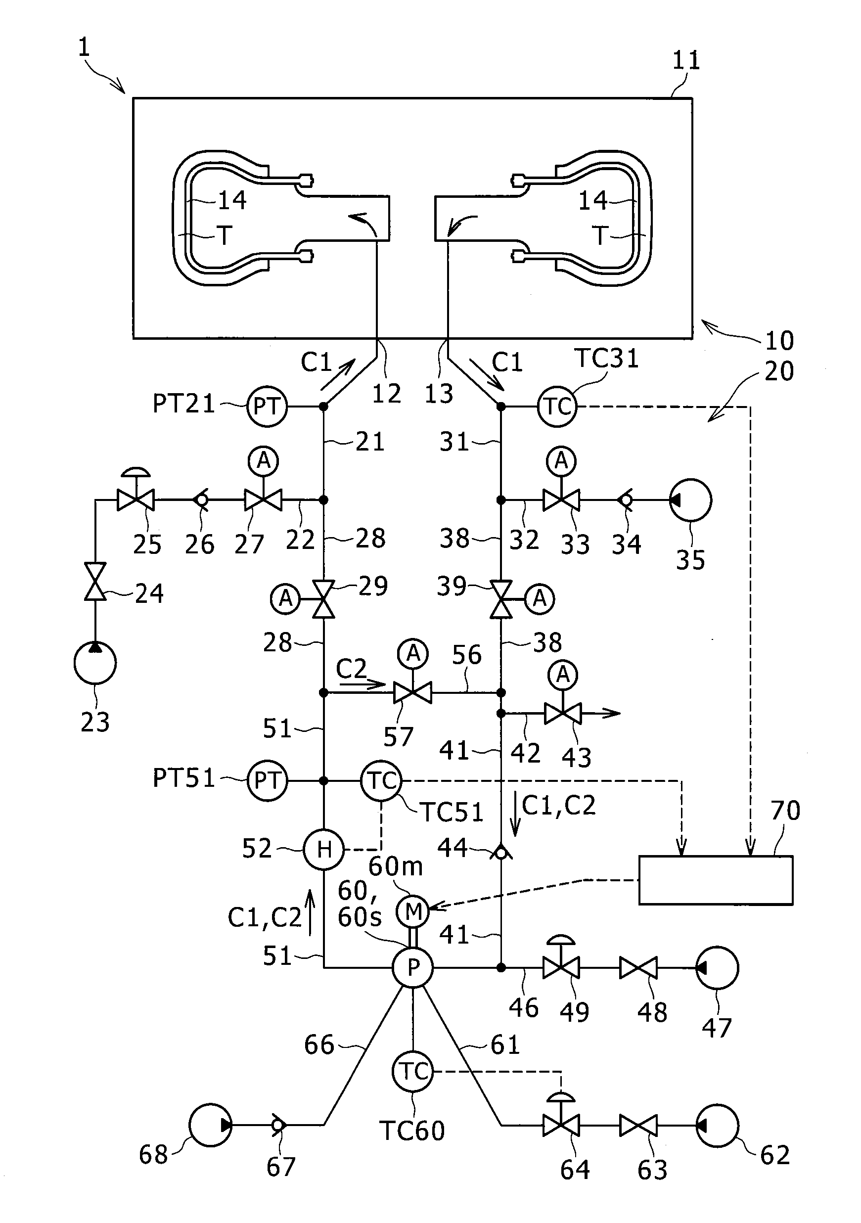
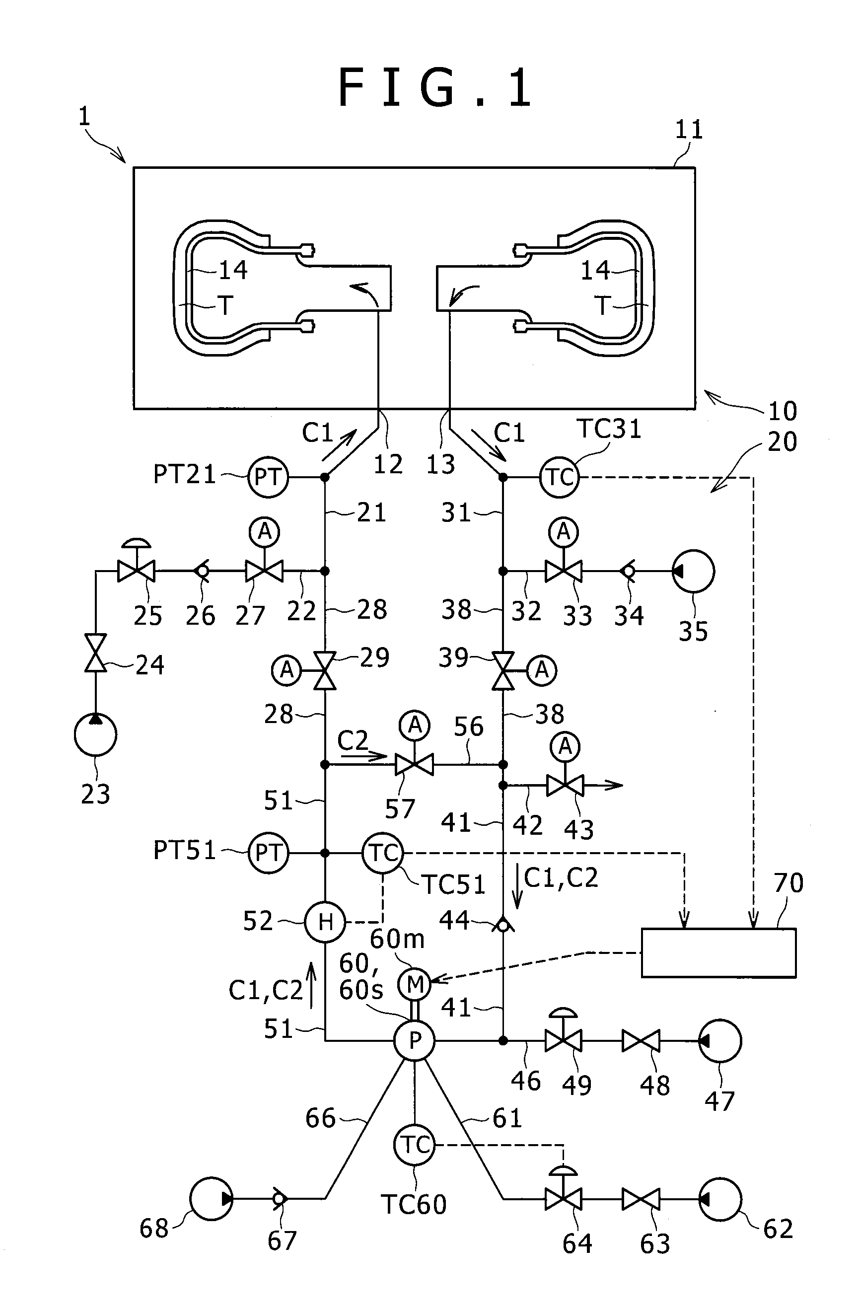
[0091]Experiment conditions of the Example are as follows. The pressure of the gas to be supplied to the supply pipe 21 (high-pressure inert gas) is 2.0 MPa. A set temperature of the heating device 52 is 220° C. The circulation device 60 is a blower having an ability of generating differential pressure of 0.14 MPa at maximum. The maximum rotating speed of the circulation device 60 is 1,750 RPM. After the start of the heating and the pressurization of the tire T, at a time point when the detected temperature of the internal outlet gas temperature sensor TC31 became 200° C., the rotating speed of the circulation device 60 was decreased from 1,750 RPM to 500 RPM.
[0092]Experiment conditions of the Comparative Example 1 are the same as the above Example in principle. However, during the vulcanization of the tire T, the circulation device 60 was continuously rotated at 1,750 RPM.
[0093]Experiment conditions of the Comparative Example 2 are as follows. As well as the i...
modified example 1
[0121]In the above embodiment, in a case where the detected temperature of the internal outlet gas temperature sensor TC31 becomes the rotating speed decrease temperature T1 or more, the controller 70, so to speak suddenly, decreases the rotating speed of the circulation device 60 (for example, from 1,750 RPM to 500 RPM). However, the controller 70 may gradually decrease the rotating speed of the circulation device 60 (modified example 1). Hereinafter, a difference between the above embodiment and the modified example 1 will be described.
[0122]A rotating speed gradual decrease temperature range T2-T1 serving as a range from a rotating speed gradual decrease start temperature T2 (second temperature) to the rotating speed decrease temperature T1 is set in the controller 70. The rotating speed gradual decrease start temperature T2 is smaller than the rotating speed decrease temperature T1. The rotating speed gradual decrease start temperature T2 is smaller than the rotating speed decre...
modified example 2
[0130]In the modified example 1, the controller 70 gradually decreases the rotating speed of the circulation device 60 in accordance with the increase in the detected temperature of the internal outlet gas temperature sensor TC31. However, the controller 70 may gradually decrease the rotating speed of the circulation device 60 in accordance with a decrease in a difference between the detected temperature of the sensor TC51 and the detected temperature of the sensor TC31 (modified example 2). Hereinafter, a difference between the modified example 1 and the modified example 2 will be described.
[0131]As described above, the heating device outlet temperature sensor TC51 (inlet gas temperature sensor) detects the temperature of the gas heated in the heating device 52 (inlet gas temperature detection step). It should be noted that this “inlet gas temperature sensor” is not necessarily provided near the outlet of the heating device 52 but may be provided in the supply pipe 21 for example.
[...
PUM
| Property | Measurement | Unit |
|---|---|---|
| Temperature | aaaaa | aaaaa |
| Energy | aaaaa | aaaaa |
Abstract
Description
Claims
Application Information