

Fuel injection controller for internal combustion engine
- Summary
- Abstract
- Description
- Claims
- Application Information
AI Technical Summary
Benefits of technology
Problems solved by technology
Method used
Image

Examples
first embodiment
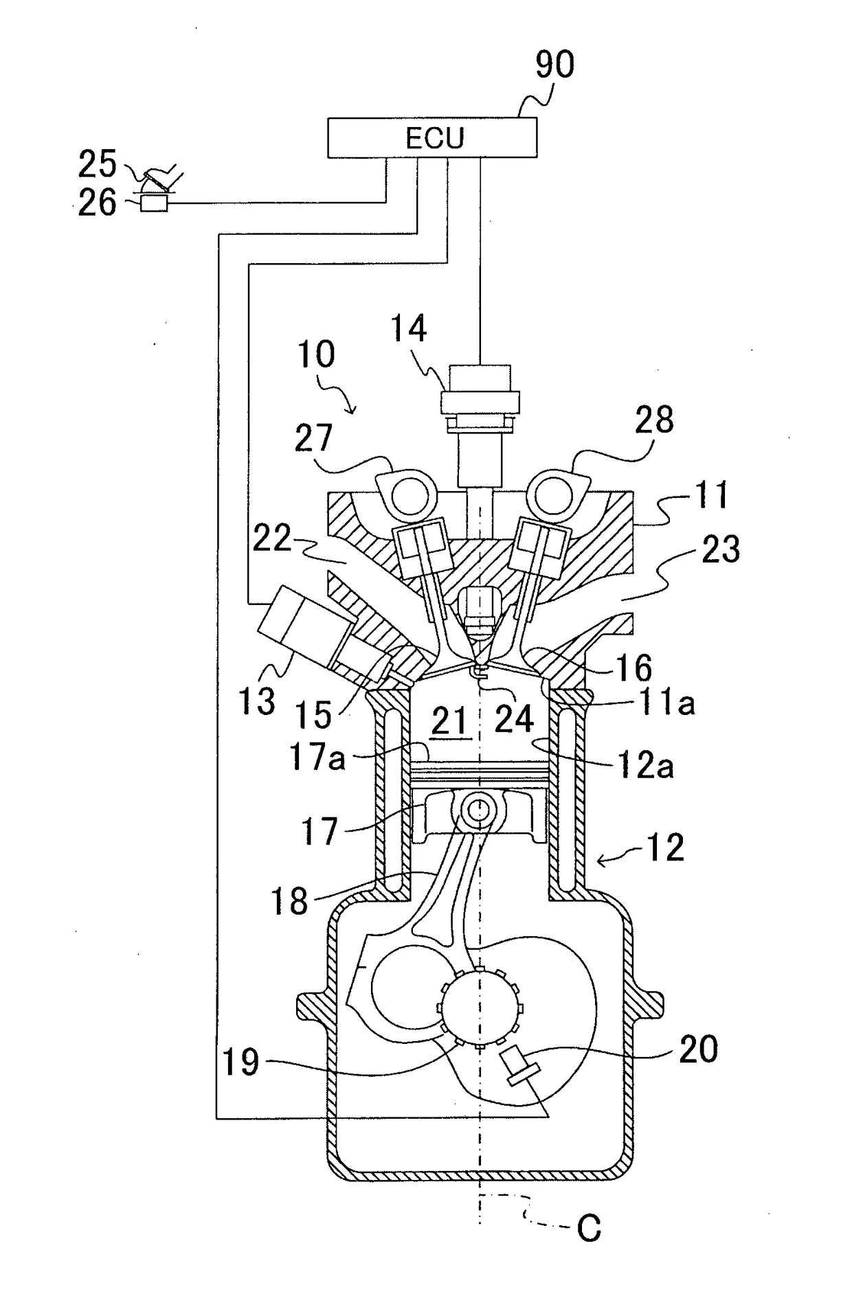
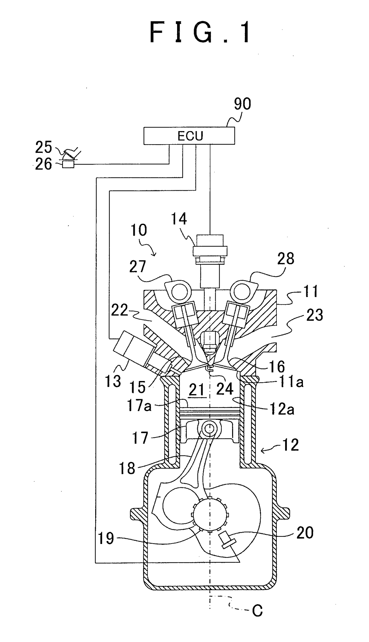
[0037]A description will hereinafter be made on a fuel injection controller (hereinafter, simply referred to as “this controller”) according to the present invention with reference to the drawings. This controller is applied to an internal combustion engine, a body 10 of which is shown in FIG. 1. The body 10 includes a cylinder head 11, a cylinder block 12, a fuel injection valve 13, an ignition system 14, an intake valve 15, an exhaust valve 16, a piston 17, a connecting rod 18, a crankshaft 19, and a crank position sensor 20. Hereinafter, a direction in which the piston 17 moves from a bottom dead center to a top dead center is referred to as “above”, and a direction in which the piston 17 moves from the top dead center to the bottom dead center is referred to as “below”. Furthermore, the intake valve 15 side from a cylinder center axis C is referred to as an “intake side”, and the exhaust valve 16 side from the cylinder center axis C is referred to as an “exhaust side”.
[0038]A co...
second embodiment
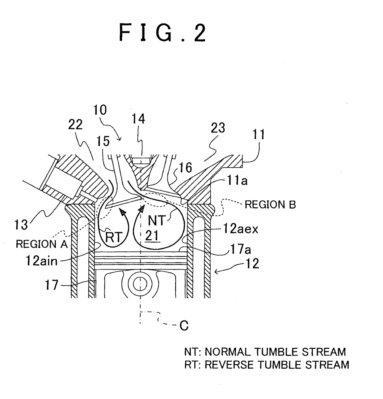
[0069]Next, a second embodiment will be described. As described above, the execution timing of the auxiliary fuel injection may be any timing as long as it is timing in the auxiliary fuel injection execution period (the specified period) Tpi. However, it is advantageous to set the execution timing of the auxiliary fuel injection in a specified period that is from “a point in time at which the intake valve 15 starts opening (a first point in time)” to “a point in time at which the lift amount of the intake valve 15 reaches the maximum lift amount of the intake valve 15 (a second point in time)” and that includes an intermediate point in time Trp between the first point in time to the second point in time.
[0070]In other words, as shown in FIG. 5B, the velocity Vrt of the reverse tumble stream RT starts increasing after the intake valve 15 starts opening, and becomes the maximum velocity at the intermediate point in time Trp between the point in time at which the intake valve 15 starts...
third embodiment
[0074]Furthermore, when the engine load is large, the total target injection amount is increased. Accordingly, when a ratio of the target main fuel injection amount to the total target injection amount remains the same, a main fuel injection amount is increased. As described above, the spray of the fuel in the main fuel injection has the large penetrating force. Accordingly, when the fuel injection amount in the main fuel injection is increased, the large amount of the fuel is eccentrically dispersed in the in-cylinder region on the exhaust side, and thus vaporization and dispersion of the fuel may not sufficiently be conducted. For this reason, it is preferred that the fuel injection amount in the auxiliary fuel injection is increased with the larger engine load. In view of the above, in the third embodiment, the number of the auxiliary fuel injection is set such that the number of the auxiliary fuel injection is increased with the larger engine load. Here, the target auxiliary fue...
PUM
 Abstract
Description
Claims
Application Information