
Friction bonding structure and pump device

Inactive Publication Date: 2013-03-14
JTEKT CORP
View PDF0 Cites 4 Cited by
  • Summary
  • Abstract
  • Description
  • Claims
  • Application Information

AI Technical Summary

Benefits of technology

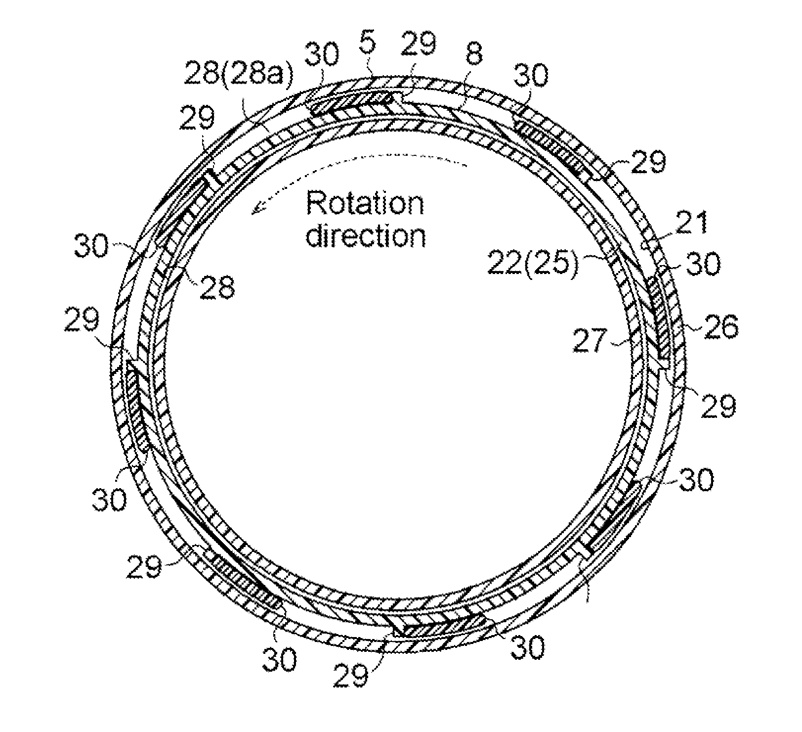
The invention offers a friction bonding structure and a pump device that can prevent burrs from sticking out without needing a bigger storage area or precise tolerances.

Problems solved by technology

Therefore, there is a possibility that the burrs will accumulate at one location and stick out of the storage portion.
This may cause cost increase.

Method used


Image

  • Friction bonding structure and pump device
  • Friction bonding structure and pump device
  • Friction bonding structure and pump device

Examples


fourth embodiment

[0050]According to the invention shown in FIG. 8, the distal ends of protrusions 47, which may function as partitioning elements, may be inclined in the direction of relative rotation between two members to be frictionally bonded together. Because the protrusions 47 are formed on the sliding contact projection 22 of the cover 8, the distal ends of the protrusions 47 are inclined in the rotation direction (counterclockwise direction in FIG. 8) of the cover 8. With this configuration, it is possible to further reliably cause the burrs 30 to adhere to the protrusions 47.

third embodiment

[0051]When protrusions, which may function as partitioning elements, are formed on (a wall portion of) the motor case 5 that is in sliding contact with the rotating cover 8 in a fixed state, the direction opposite to the rotation direction of the cover 8 is the “relative rotation direction”. Therefore, for example, if the configuration in the third embodiment shown in FIG. 7 is employed as the base configuration, the distal ends of the protrusions 44 need to be inclined in the clockwise direction.

[0052]In the first and second embodiments and the third and fourth embodiments shown in FIG. 7 and FIG. 8, the protrusions (29, 44 or 47), which may function as partitioning elements, are arranged in the storage portion 28a located radially outward of the friction bonded portion 25. However, the invention is not limited to this configuration. When the burrs 30 tend to be produced on the radially inner side of the friction bonded portion 25, as according to a fifth embodiment of the inventio...

sixth embodiment

[0053]According to the invention, partitioning elements are arranged in both the storage portions 28a, 28b located on the radially outward and inward of the friction bonded portion 25, respectively. As shown in FIG. 10, a plurality of protrusions 53 and a plurality of protrusions 54 are formed radially outward and inward of a sliding contact projection 52, respectively. The storage portion 28a and the storage portion 28b located radially outward and inward of the friction bonded portion 25 are partitioned in the circumferential direction by the protrusions 53 and the protrusions 54, which may function as partitioning elements, respectively. Alternatively, a plurality of protrusions is formed on at least one of the wall portions of the annular groove so that at least one of partitioning elements arranged in the outer-side storage portion 28a and partitioning elements arranged in the inner-side storage portion 28b are formed of the protrusions formed on the at least one of the wall po...


PUM

PropertyMeasurementUnit
Structureaaaaaaaaaa
Frictionaaaaaaaaaa

Abstract

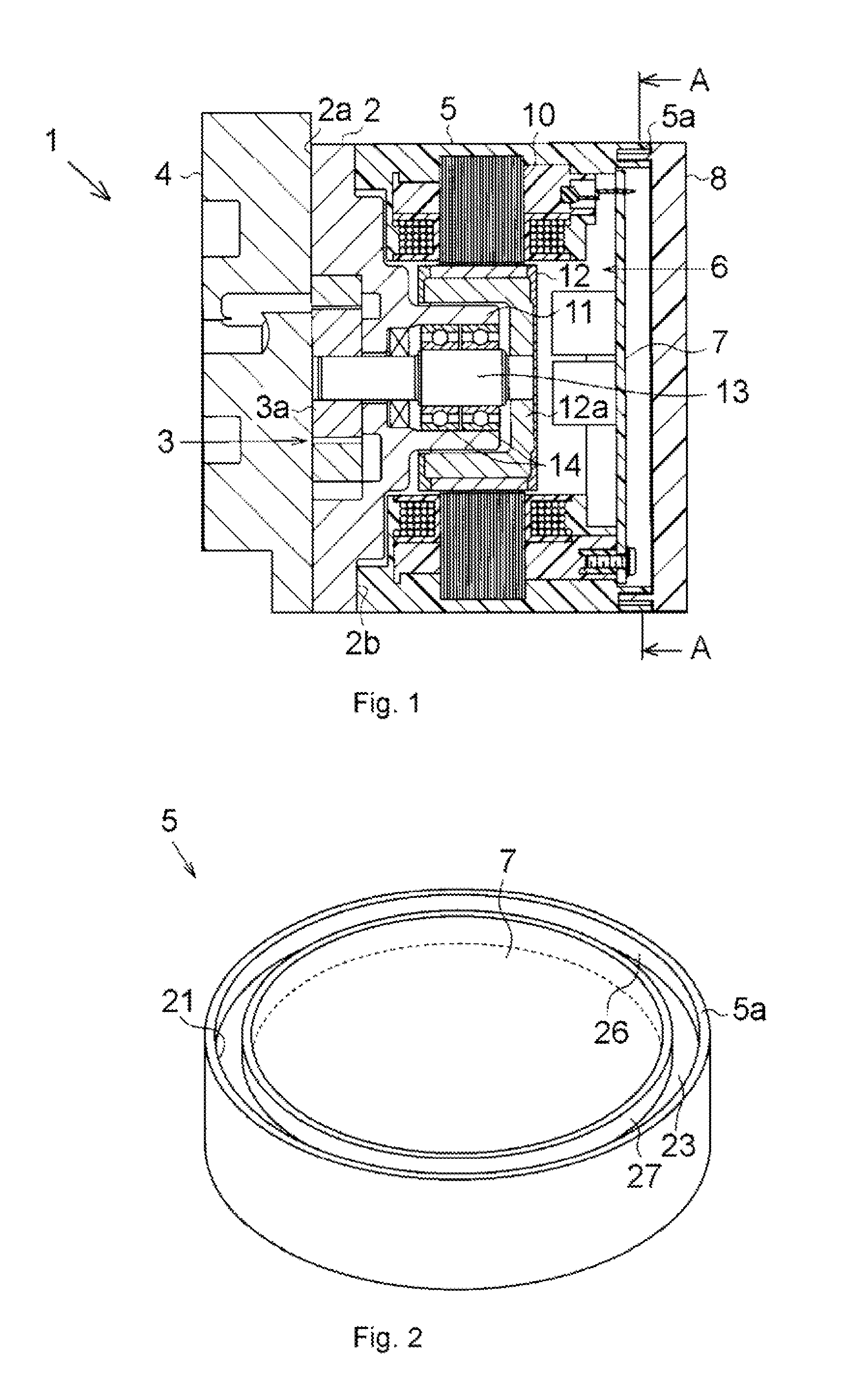
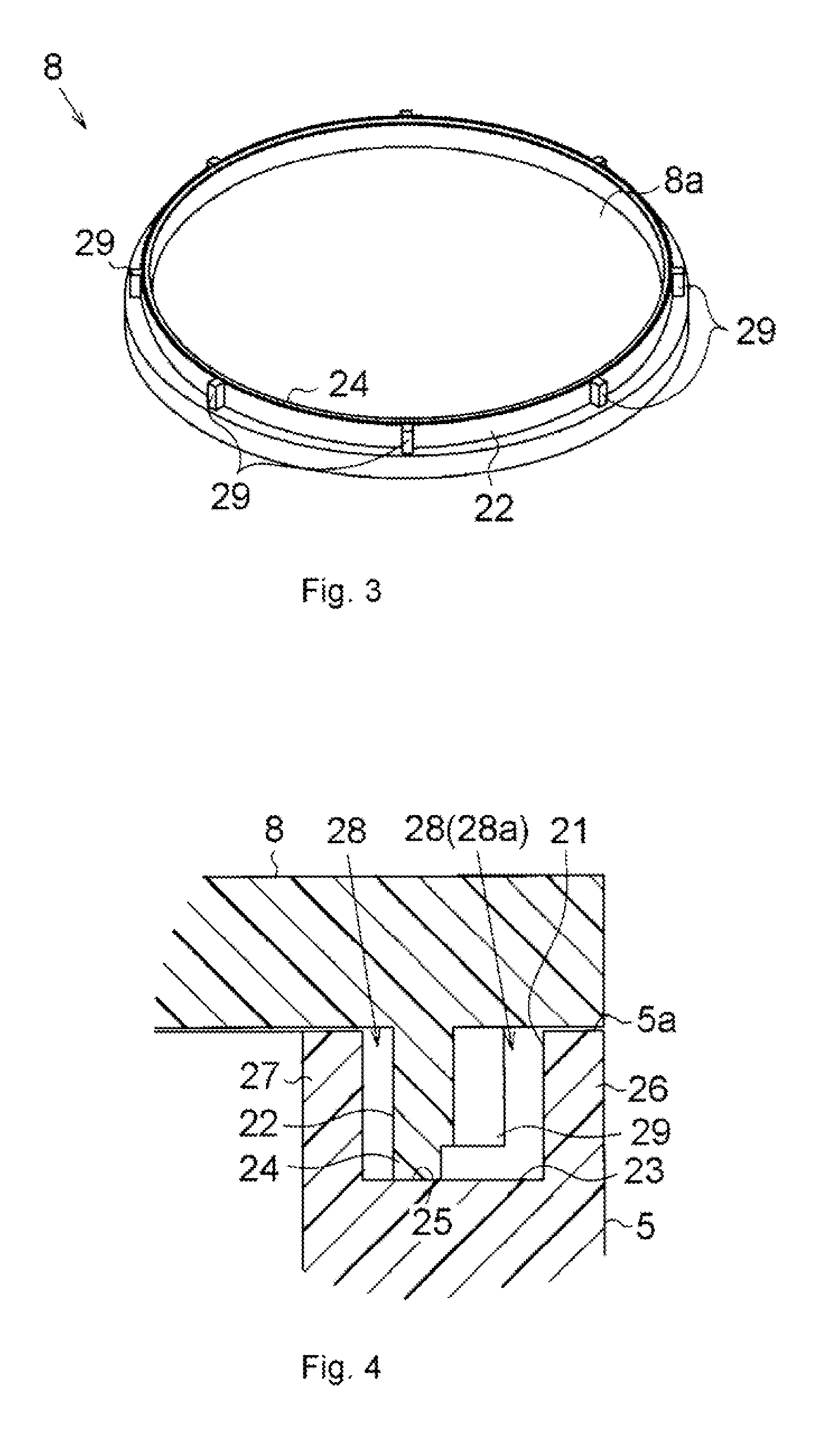
An annular groove is formed at an open end of a motor case, and a sliding contact projection, which is in an annular plate-shape and corresponding to the annular groove, is formed on a cover. A bottom of the annular groove and the sliding contact projection rotate relative to each other while being in sliding contact with each other to form an annular friction bonded portion therebetween. Wall portions of the annular groove are arranged at such positions as to be concentric with the friction bonded portion. Thus, a storage portion that stores burrs produced at the friction bonded portion is formed. A plurality of protrusions that protrude radially outward is formed on the sliding contact projection over all around. The storage portion is partitioned in the circumferential direction by using the protrusions as partitioning elements.

Description

INCORPORATION BY REFERENCE / RELATED APPLICATION[0001]This application claims priority to Japanese Patent Application No. 2011-198539 filed on Sep. 12, 2011 the disclosure of which, including the specification, drawings and abstract, is incorporated herein by reference in its entirety.BACKGROUND OF THE INVENTION[0002]1. Field of the Invention[0003]The invention relates to a friction bonding structure and a pump device.[0004]2. Discussion of Background[0005]There are conventional methods of bonding contact portions of two members together by utilizing frictional heat generated between the two members Such methods include, for example, ultrasonic welding and spin welding. Employment of such friction bonding provides a bonded portion, at which the two members are bonded together, with high sealing performance.[0006]However, if the meltage is increased in order to ensure high sealing performance, the amount of products of melting, which stick out from the bonded portion, that is, the amou...

Claims


Application Information

Patent Timeline
IPC IPC(8): B23K20/12
CPCB23K20/129F01C19/005F01C21/10F04C2/10Y10T403/477F04C2230/20F04C2230/60F04C2230/70F04C15/0034B29C65/0672B29C66/124B29C66/322B29C66/542B29C66/71B29L2031/749B29K2077/00
Inventor TOYAMA, YUICHI
Owner JTEKT CORP
Learn More