Steam turbine

a steam turbine and axial cross-flow technology, which is applied in the direction of friction gearings, water acting propulsive elements, bearings, etc., can solve the problems of poor efficiency, high wattage and high cost of axial flow steam turbines with axial cross-flow, and achieve the effect of large gear ratio

Inactive Publication Date: 2013-03-14
BIO SYST FUR ANWENDUNGEN BIOLOGISCHER VERFAHREN MBH
View PDF2 Cites 1 Cited by
  • Summary
  • Abstract
  • Description
  • Claims
  • Application Information

AI Technical Summary

Benefits of technology

[0027]Preferably, the hollow shaft comprises a force output-side that is disposed between the engagement circumferences with the planetary gear sets. The force output-side is advantageously disposed in a narrowing between the regions where the hollow shaft is in contact on the inner side with the planetary friction gears. This offers the advantage of a large gear ratio.
[0028]Preferably, the hollow shaft or the planetary gears or the shaft comprise a collar for axially guiding the shaft or the hollow shaft. This offers the advantage of the shaft to be simply supported in the axial direction.

Problems solved by technology

It is disadvantageous that such axial flow steam turbines can only be constructed for high wattages, if expenditures and efficiency are to be maintained in an acceptable range.
For smaller mass flows, such axial flow steam turbines with axial cross-flow are expensive and may suffer, moreover, from poor efficiency.
However, the apparatus with radial flow-off shown therein only demonstrates limited efficiency in applications involving low mass flows.

Method used


Image

  • Steam turbine
  • Steam turbine
  • Steam turbine

Examples


Embodiment Construction

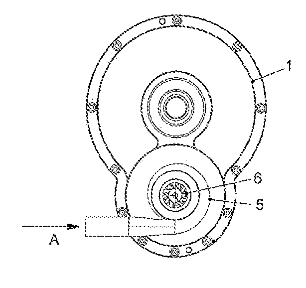
[0038]FIG. 1 shows a schematic side view of a steam turbine according to the invention with an apparatus according to the invention for supporting a shaft. The steam turbine comprises a housing of which FIG. 1 only includes a representation of one half of the housing 1.

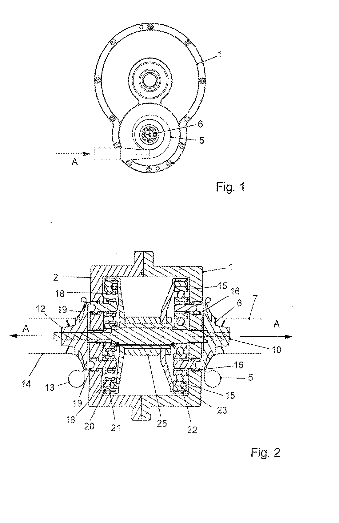
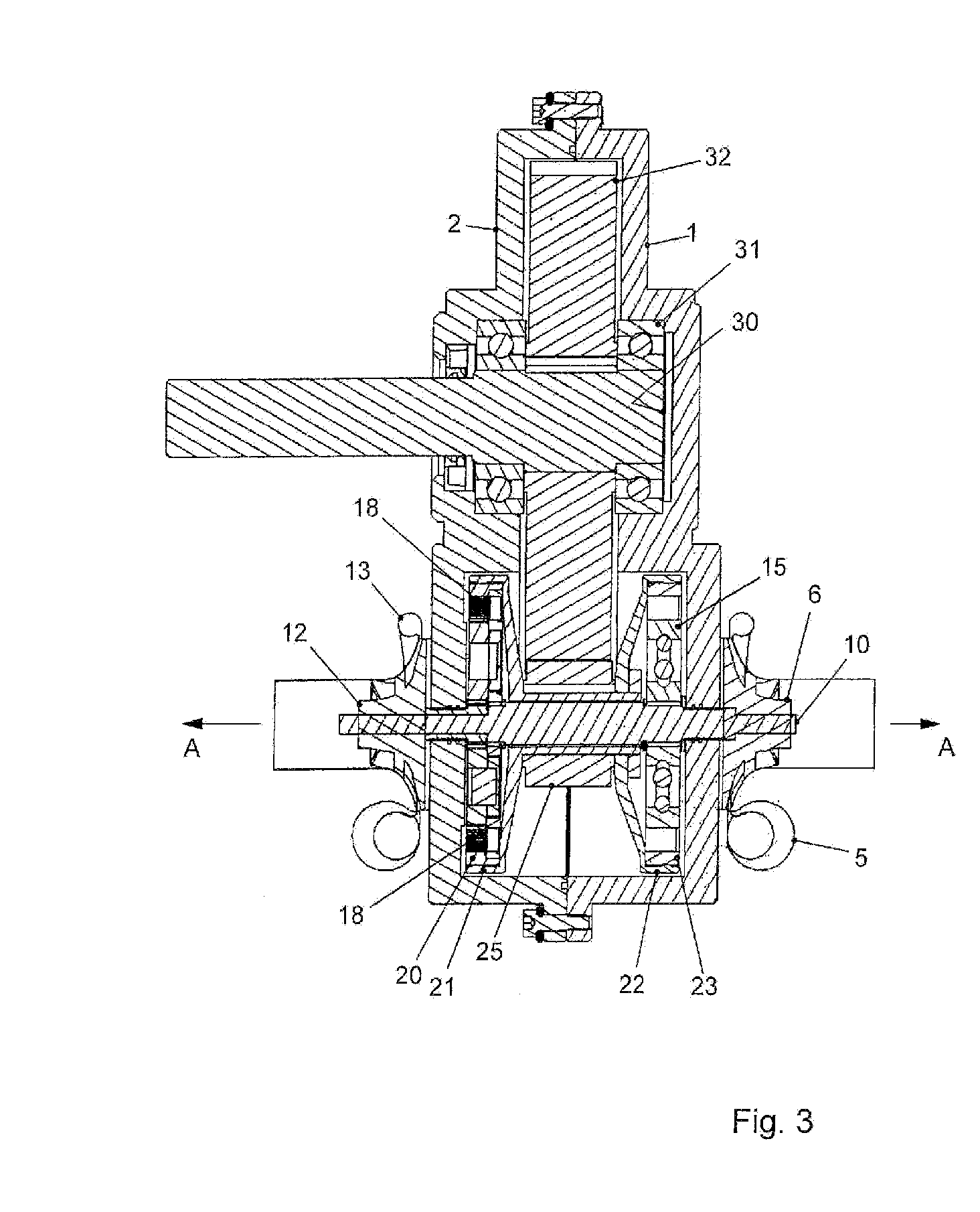
[0039]FIG. 2, which will be explained in connection with FIGS. 1 and 3, shows a section through the steam turbine of FIG. 1, wherein identical reference symbols in FIGS. 1 to 3 represent identical or similar parts herein and are not necessarily repeated for each description of a figure.

[0040]FIG. 2 also shows a sectional representation of the housing half 1, wherein the section of FIG. 2 extends through the lower region of the steam turbine of FIG. 1. Furthermore, FIG. 2 shows a second housing half 2 that is connected to the first housing half 1 by a flanged connection.

[0041]FIG. 1 contains, moreover, as a schematic top view, a first inlet screw 5, which is part of a steam inlet for impinging a first radial flow wheel...


PUM


Abstract

A steam turbine having a mechanical power rating of up to 500 kW for powering a generator having a shaft, a steam inlet, and an open radial flow wheel, which is torque-resistantly connected to the shaft and can be impinged with steam by the steam inlet.

Description

RELATED APPLICATIONS[0001]This application is a national phase filing of PCT / EP2011 / 058296 and as such claims priority to German Patent Application Serial Number 102010017061.5 filed May 21, 2010, which is herein incorporated by reference.FIELD OF THE INVENTION[0002]The invention relates to a steam turbine, and in particular to a steam turbine according to the preamble of claim 1, as well as an apparatus for supporting a shaft according to a further independent claim herein.BACKGROUND[0003]Steam turbines that convert thermal energy from steam, particularly superheated steam, into mechanical energy, which can then be converted further to electrical energy by means of a generator, are known from the prior art. Steam turbines of this kind are also known for small effective power values, meaning for wattages below 500 kW, wherein steam turbines that are known from the prior art have a shaft which has turbine blades disposed thereon. Steam is routed via a steam inlet in axial direction t...

Claims


Application Information

Patent Timeline
Patent Type & Authority Applications(United States)
IPC IPC(8): F01D3/02F16H13/08F01D5/04
CPCF01D3/025F01D5/043F05D2210/43F05D2220/31F16C19/50
Inventor FREHLAND, ECKART
Owner BIO SYST FUR ANWENDUNGEN BIOLOGISCHER VERFAHREN MBH
Why Eureka
Try Eureka