
Flat tubular solid oxide fuel cell stack

a fuel cell and flat tubular technology, applied in the field of flat tubular solid oxide fuel cell stacks, can solve the problems of more reduced contact area for conduction, and achieve the effects of increasing contact area, stable electrical contact, and smooth supply of air

Active Publication Date: 2013-03-14
KOREA ADVANCED INST OF SCI & TECH
View PDF1 Cites 5 Cited by
  • Summary
  • Abstract
  • Description
  • Claims
  • Application Information

AI Technical Summary

Benefits of technology

The present invention is a flat tubular solid oxide fuel cell stack that uses a connection member to smoothly supply air and increase the contact area, resulting in stable electrical contact. The fuel cells have cut-parts formed in a plate shape member, which increases productivity and allows for stable contact even in fuel cells with uneven surfaces and large areas. Additionally, a spacing member is included to easily move air and support the fuel cell, making the fuel cell durable in both horizontally and vertically multilayered forms.

Problems solved by technology

In particular, in the case in which the fuel cell having a large area is formed, a surface thereof may frequently be uneven or bent, such that the contact area for conduction is more decreased.

Method used


Image

  • Flat tubular solid oxide fuel cell stack
  • Flat tubular solid oxide fuel cell stack
  • Flat tubular solid oxide fuel cell stack

Examples


Embodiment Construction

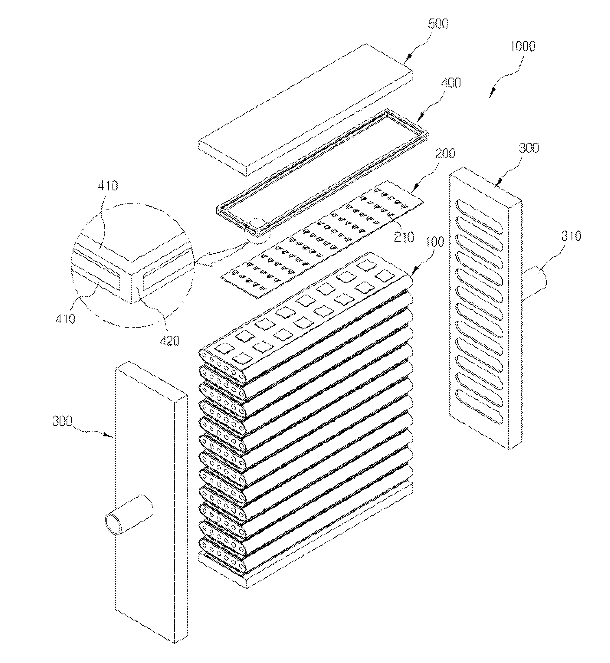
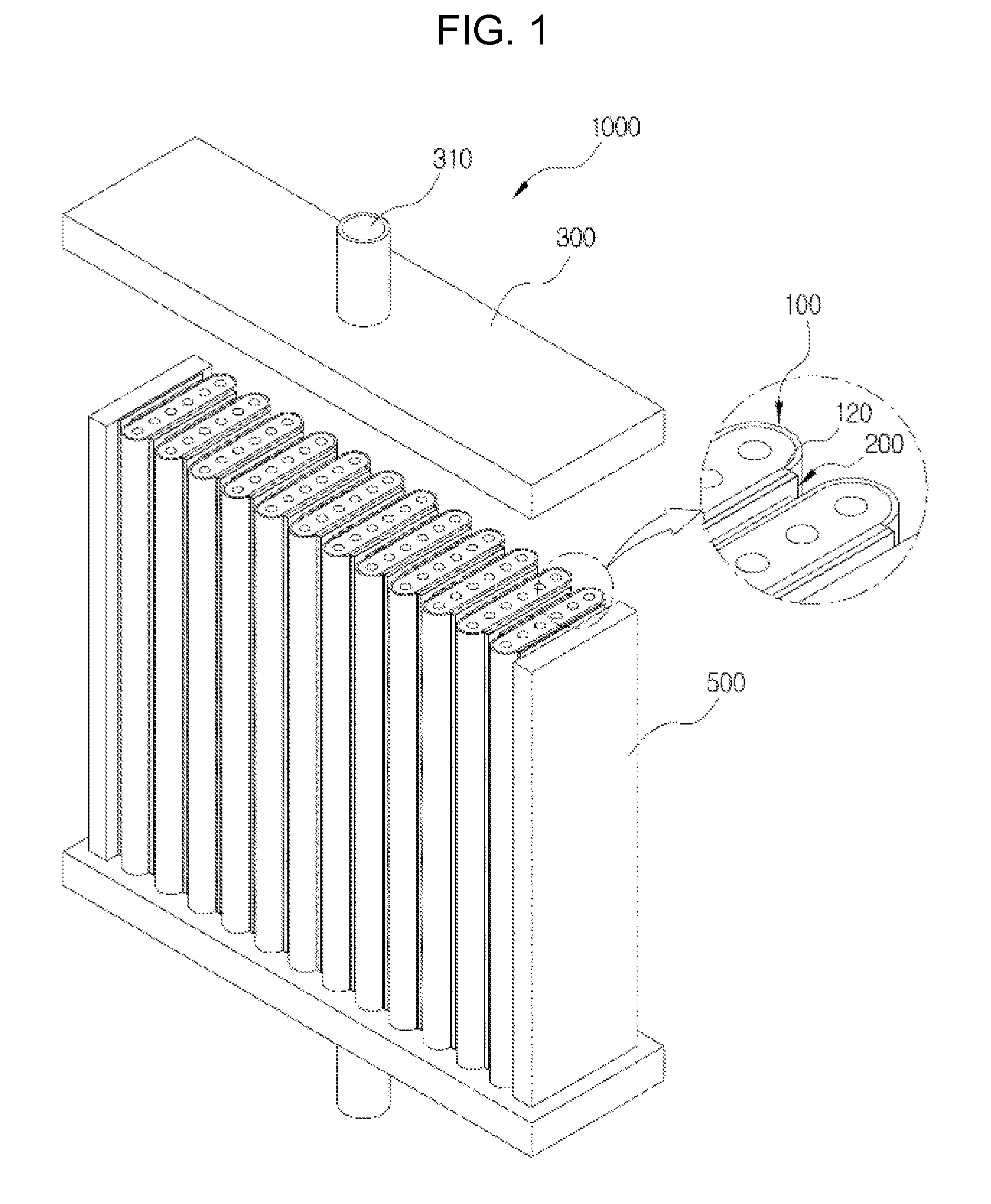
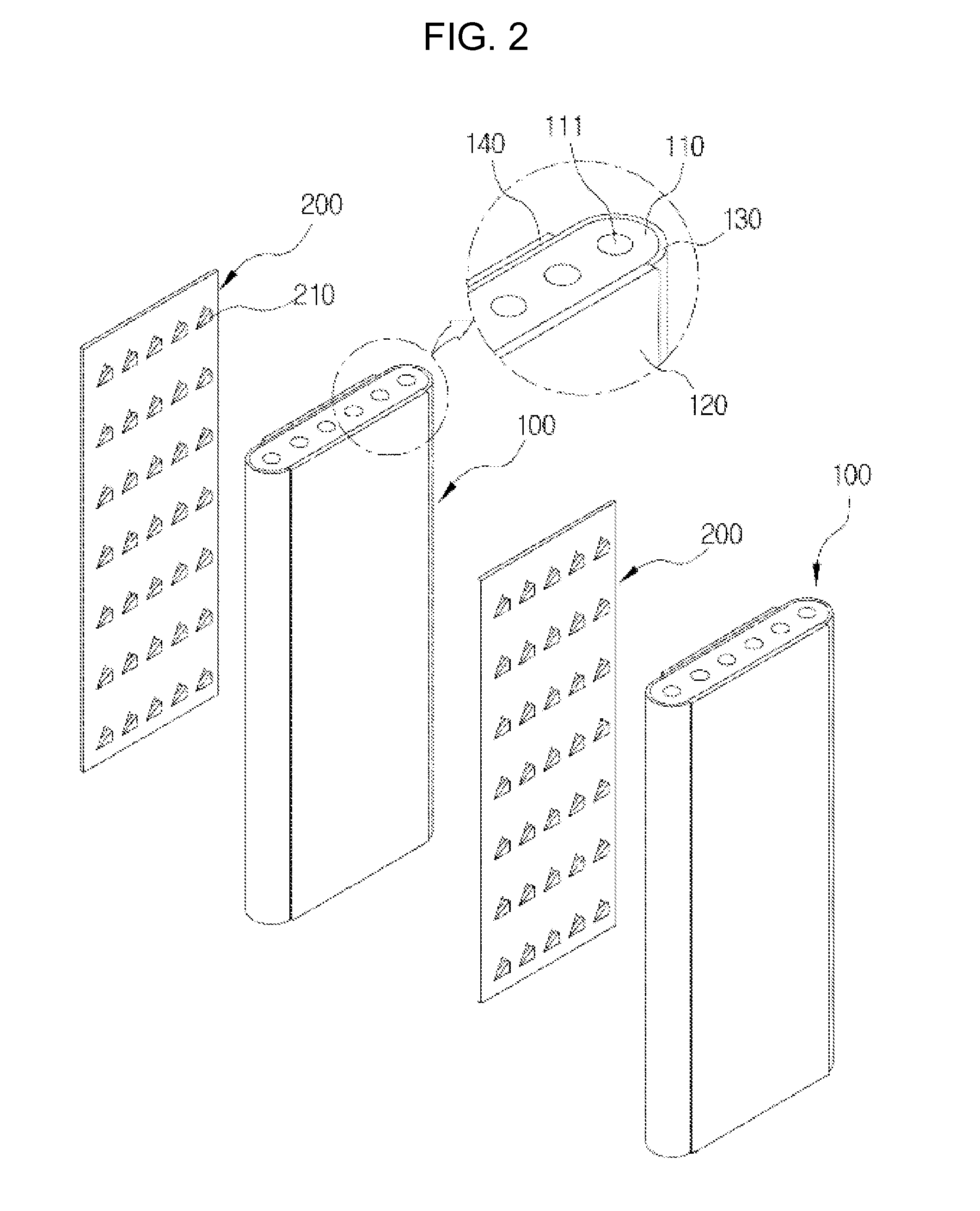
of Main Elements]1000: FLAT TUBULAR SOLID    OXIDE FUEL CELL    STACK 100: FUEL CELL 110: ANODE SUPPORT111: FUEL TRANSFER HOLE 120: CONNECTING LAYER121: FIRST CONNECTING LAYER 122: SECOND CONNECTING    LAYER 130: ELECTROLYTE LAYER 140: CATHODE 200: CONNECTION MEMBER210: CUT-PART 300: MANIFOLD310: FUEL SUPPLY PART 400: SPACING MEMBER 420: HEIGHT-FORMING PART 500: COLLECTING MEMBER

BEST MODE

[0030]Hereinafter, a flat tubular solid oxide fuel cell stack 1000 of the present invention having the above-described characteristics will be described in detail with reference to the accompanying drawings.

[0031]The flat tubular solid oxide fuel cell stack 1000 of the present invention includes a fuel cell 100, a connection member 200, and a manifold 300.

[0032]The fuel cell 100 is one unit including an anode support 110, a connecting layer 120, an electrolyte layer 130, and a cathode 140. The anode support110 has a plurality of fuel transfer holes 111 which transfers a fuel thereinto and is formed ...


PUM

PropertyMeasurementUnit
widthaaaaaaaaaa
distanceaaaaaaaaaa
heightaaaaaaaaaa

Abstract

Provided is a flat tubular solid oxide fuel cell stack, and more particularly, a flat tubular solid oxide fuel cell stack in which a connection member is interposed between a plurality of fuel cells to smoothly supply air and increase a contact area, in order to enable a stable electrical contact.

Description

TECHNICAL FIELD[0001]The present invention relates to a flat tubular solid oxide fuel cell stack, and more particularly, to a flat tubular solid oxide fuel cell stack in which a connection member is interposed between a plurality of fuel cells to smoothly supply air and increase a contact area, in order to enable stable electrical contact.BACKGROUND ART[0002]A fuel cell, which is a cell directly converting chemical energy produced by oxidation of electrical energy, is a novel, environment-friendly, and futuristic energy technology generating electrical energy from materials existing abundantly on earth, such as hydrogen and oxygen.[0003]In a fuel cell stack, oxygen is supplied to a cathode, hydrogen is supplied to an anode, and an electrochemical reaction, which is a reverse reaction of electrolysis of water is performed to generate electricity, heat, and water, such that pollution is not generated and electrical energy is produced in high-efficiency.[0004]Since the fuel cell stack ...

Claims


Application Information

Patent Timeline
Patent Type & Authority Applications(United States)
IPC IPC(8): H01M8/24H01M8/04
CPCH01M8/0247H01M8/2425H01M2008/1293H01M8/006Y02E60/525H01M8/004Y02E60/50H01M8/2432H01M8/2457H01M8/2484H01M8/243
Inventor BAE, JOONG MYEONPARK, JOON GUEN
Owner KOREA ADVANCED INST OF SCI & TECH
Learn More