Air management for enhancing pneumatic rebound training

a rebound training and air management technology, applied in the field of stationary versions of pneumatic rebound exercise devices, can solve the problems that the leakage of air from the system was not appreciated by users, and achieve the effect of enhancing aerobic and anaerobic conditioning

Active Publication Date: 2013-03-14
PLYO SYST
View PDF17 Cites 2 Cited by
  • Summary
  • Abstract
  • Description
  • Claims
  • Application Information

AI Technical Summary

Benefits of technology

[0010]The most novel feature described in the referenced patent by this inventor, allows the automatic upward extension, or lengthening of the air spring / cylinders(s) whenever the movable part of the apparatus is drawn far enough upward by the energetic bounding efforts of the exerciser. This motion creates a partial vacuum that draws more air into the spring / cylinders through check valves, effectively lengthening the air springs. It was found early on in the development of that invention that the check valves used needed to have the lowest “cracking pressure” available, which is the pressure at which the valve opens, allowing, in this case, air to be drawn into the cylinders. This ‘pumping-in’ of air is what allows the exerciser to bounce higher, which explains the need for a very low cracking pressure; otherwise, very few people would be able to operate the equipment as designed. When it is desired to descend, a valve is opened that bleeds air from the spring / cylinders. This “descent valve” is either a manual push-button bleeder valve or a common ball valve in all the early prototypes, as well as many of the later versions.
[0011]In the years that followed the above-mentioned original patent application process, many improvements were made in the machine design, most of which were focused on reducing friction in the air-spring / cylinders so that the bounding motion could be as free and easy as possible for the user. Much of the resulting reduction of friction was accomplished by reducing the suggested interference, or tightness between the bore of the cylinder and the U-cup piston seal. Although the friction was reduced considerably in this way, we found that there was a fine line between low friction and air leakage past the seal, and we had already seen that any leakage of air from the system was not appreciated by the users, as the air thus leaked had to be replaced by energetic efforts. Most of this early development was done by trial and error, as there were no precedents to be found for push-stroke air cylinders used in this way as low-friction air springs.
[0012]The high side-loads on the bearing surfaces required oversize, low friction bearings, even after the next notable improvement: that of joining two of the above-described spring / cylinders by rigidly attaching a footrest platform and handlebar between them. Compared with the earlier, single-cylinder designs shown in the early patent above-referenced, that change also greatly reduced the friction caused by side-loading of the sliding surfaces. This improvement not only increased the life expectancy of the machines by several times, but also made the bounding exercise easier and more enjoyable for the average exerciser, and for longer periods of use.
[0018]The main object of the present invention is to provide professional and commercial viability for pneumatically elevating rebound exercise devices. In order to accomplish this objective, it provides:A wide range of repeatable levels of difficulty for cardiovascular exercise,Several options for achieving different exercise difficulty levels, andA capability for timed interval training for improving cardiovascular fitness, producing Comparative benchmarks of cardiovascular capacity for the athletes and their coaches.Motivation for athletes to improve and exceed previous efforts on the equipment.Encouragement for exercise competition between athletes.Virtually unlimited degrees of exertion, varying from gentle aerobic exercise levels for the casual exerciser, through anaerobic High-Intensity Interval Training (HIIT) levels for competitive athletes,Mitigated impact levels for high intensity plyometric (jumping) exercise, and Increased Range-Of-Motion (ROM) control.

Problems solved by technology

Although the friction was reduced considerably in this way, we found that there was a fine line between low friction and air leakage past the seal, and we had already seen that any leakage of air from the system was not appreciated by the users, as the air thus leaked had to be replaced by energetic efforts.
Most of this early development was done by trial and error, as there were no precedents to be found for push-stroke air cylinders used in this way as low-friction air springs.

Method used


Image

  • Air management for enhancing pneumatic rebound training
  • Air management for enhancing pneumatic rebound training

Examples


Embodiment Construction

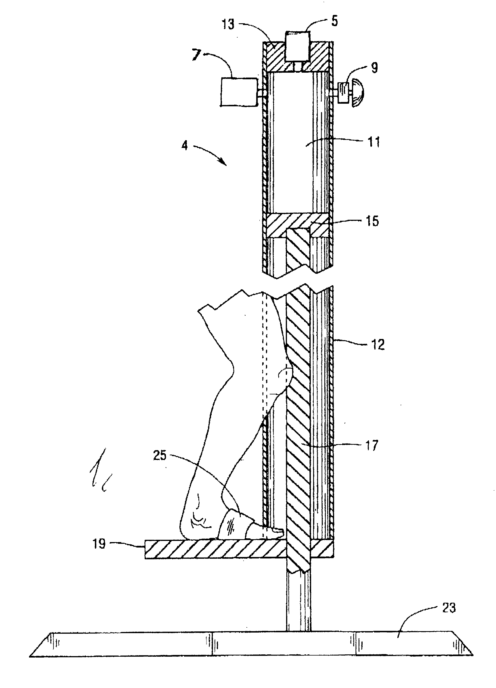
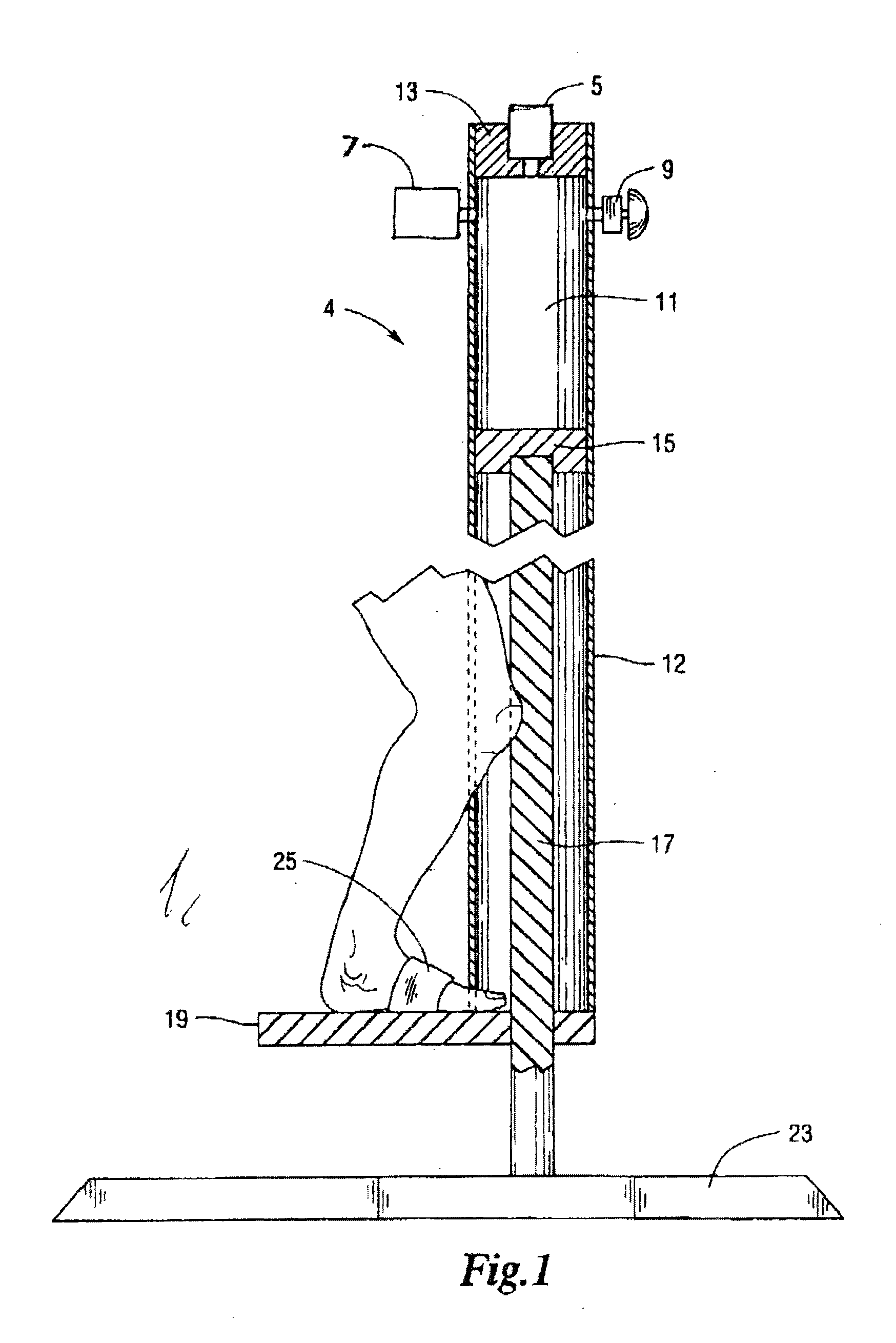
[0033]The FIGURE shows a schematic view of a basic form of the invention. An extendable air spring 4 is shown connected to a base / stand 23 by way of a piston rod 17 which is connected to piston 15. The piston sealingly slides inside cylinder barrel 12, which is sealingly closed off at the top by a cylinder head 13. An extendable air compression chamber 11 is thus defined and confined inside the cylinder barrel 12 and between the piston 15 and cylinder head 13. A foot strap 25 is connected to a footrest platform 19 which rigidly connects to the bottom of the cylinder barrel 12 and is shown being acted upon by a leg of an exercising user. The FIGURE also shows three different air valves opening into the air compression chamber 11: adjustable intake check valve 5, adjustable bleed valve 7 (a needle-type metering valve in the preferred embodiment), and a normally closed, push-type descent valve 9.

[0034]The basic operation is as follows: In the FIGURE, a leg of an exercising user is show...


PUM


Abstract

An air management system that allows safe and convenient forms of interval training exercise to be performed on pneumatically elevating rebound exercise equipment. The system includes at least one air intake valve and bleed valve. By providing repeatable degrees of difficulty for both air intake and air release from the extendable air springs employed for the exercise, competitive athletes and their coaches can design, employ, repeat, and compare individualized medium- or high-intensity interval protocols for optimal cardiovascular training programs.

Description

CROSS-REFERENCE TO RELATED APPLICATIONS[0001]This patent application is a divisional of U.S. application Ser. No. 11 / 604,087, filed Nov. 25, 2006, which claims the benefit under 35 U.S.C §119(e) of U.S. Provisional Application No. 60 / 739,674, filed Nov. 25, 2005, each of which is incorporated herein by reference in its entirety.STATEMENT REGARDING FEDERALLY SPONSORED RESEARCH OR DEVELOPMENT[0002](Not applicable)REFERENCE TO SEQUENTIAL LISTING, A TABLE, OR A COMPUTER PROGRAM LISTINGAPPENDIX SUBMITTED ON A COMPACT DISC[0003](Not applicable)BACKGROUND OF THE INVENTION[0004]1) Field of the Invention[0005]This application relates to stationary versions of pneumatic rebound exercise devices.[0006]2) Description of the Related Art[0007]The closest prior art known to me are the following U.S. patents which were deemed pertinent: U.S. Pat. Nos. 4,124,202, 4,632,371, 5,628,496, 5,810,125, 5,887,857, 5,915,674, 5,921,899, 6,267,360, 6,446,943, 6,468,190, and 7,011,608. Also, patents for variou...

Claims


Application Information

Patent Timeline
Patent Type & Authority Applications(United States)
IPC IPC(8): A63B21/00F16K24/00
CPCA63B5/16A63B21/00069F16K24/00A63B25/08A63B21/00036A63B21/0087Y10T137/309
Inventor MORROW, GEORGE STEVEN
Owner PLYO SYST
Why Eureka
Try Eureka