Real-time monitoring of electric power system voltage stability margins

a technology of electric power system and voltage stability, applied in the direction of electric variable regulation, process and machine control, instruments, etc., can solve problems such as system voltage instability, voltage drop undergoes dramatic decline, and voltage stability is treated as a major threa

Inactive Publication Date: 2013-03-14
QUANTA ASSOC
View PDF3 Cites 40 Cited by
  • Summary
  • Abstract
  • Description
  • Claims
  • Application Information

AI Technical Summary

Benefits of technology

[0047]The disclosure describes a method, apparatus and program for real-time calculation and monitoring of voltage stability margin of the electric power system. Based on the measurements of phasor data, the P-Q curve is updated and the active, reactive and apparent power margins are calculated and moni...

Problems solved by technology

Power system voltage instability is caused by inability of the combined generation and transmission system to deliver power requested by loads.
Voltage stability is treated as a major threat for secure operation of the power system.
In a voltage unstable situation, the voltage drops undergo a dramatic decline in the minutes following disturbance.
If this decrease is too pronounced, the system integrit...

Method used


Image

  • Real-time monitoring of electric power system voltage stability margins
  • Real-time monitoring of electric power system voltage stability margins
  • Real-time monitoring of electric power system voltage stability margins

Examples


embodiment 1

Method Embodiment 1

Real-Time Monitoring of Voltage Stability Margins

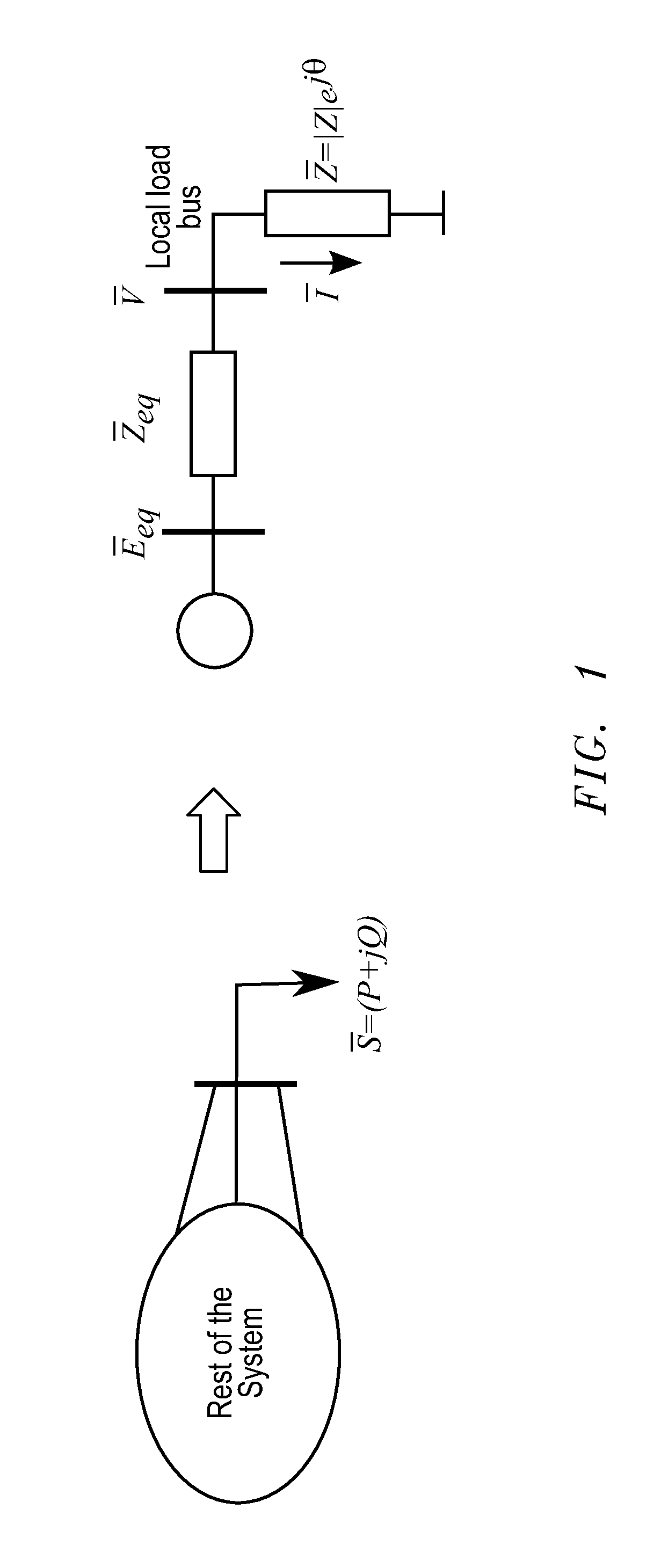
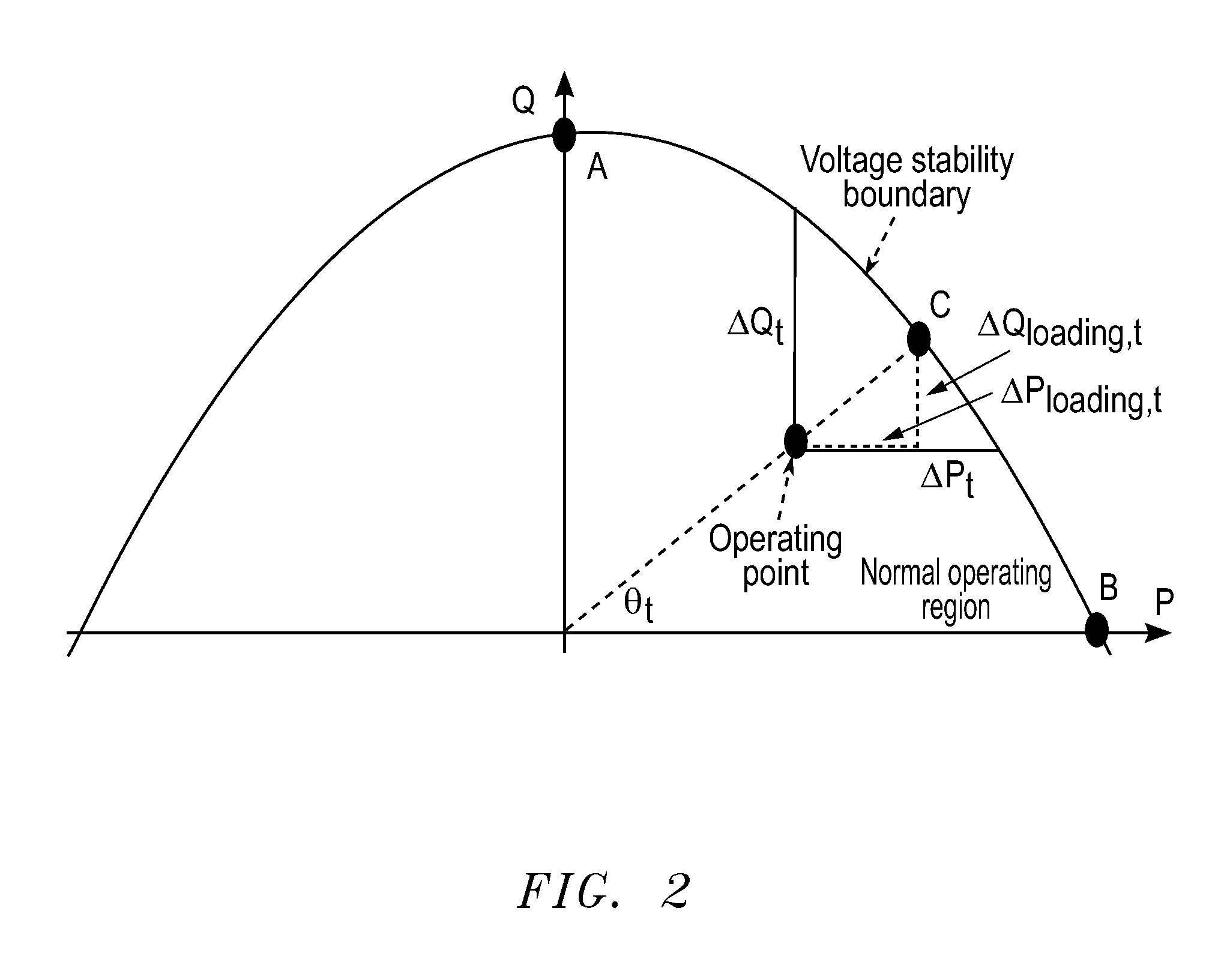
[0081]1. At time t:[0082]a. Calculate equivalent parameters Ēeq,t and Zeq,t [0083]b. Calculate the load impedance Zt [0084]2. Calculate Pmax,t, Qmax,t and Smax,t from equations (18), (19), and (15), respectively[0085]3. Calculate parameters at, bt and ct of the parabola Qmax,t=at·Pmax,t2+bt·Pmax,t+ct using equation (21) and least squares method (23)[0086]4. Calculate the power margins ΔPt, ΔQt, ΔSt using equations (24)[0087]5. Set t→t+1 and go to step 1.

[0088]Another preferred embodiment is to use the voltage stability margin in combination with load shedding. For this preferred embodiment, the description of this method is given below

embodiment 2

Method Embodiment 2

Real-Time Monitoring of Voltage Stability Margins with Load Shedding

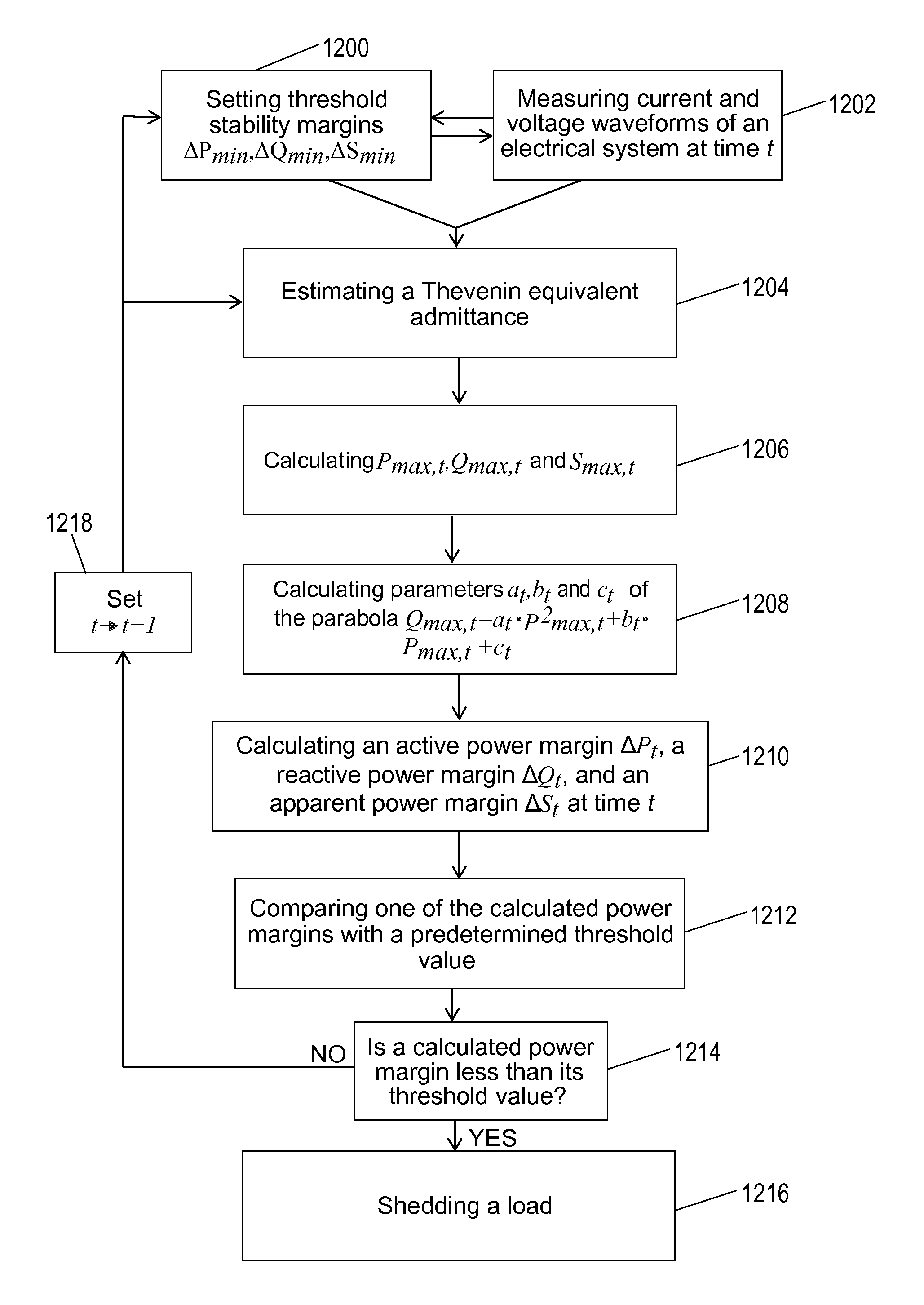
[0089]1. Set the threshold stability margins ΔPmin, ΔQmin, ΔSmin that will be used as a trigger point for load shedding initialization. It is assumed that only one of these three threshold values will be used as a trigger point for load shedding.[0090]2. At time t:[0091]a. Calculate equivalent parameters Ēeq,t and Zeq,t [0092]b. Calculate the load impedance Z,t [0093]3. Calculate Pmax,t, Qmax,t and Smax,t from equations (18), (19), and (15), respectively[0094]4. Calculate parameters at, bt and ct of the parabola Qmax,t=at·Pmax,t2+bt·Pmax,t+ct using equation (21) and least squares method (23)[0095]5. Calculate the power margins ΔPt, ΔQt, ΔSt using equations (24)[0096]6. If selected margin is smaller than a threshold value (for instance: ΔPtmin) start Load Shedding process; otherwise proceed to the next step, 7.[0097]7. Set t→t+1 and go to step 1.

[0098]Various preferred embodiments are further liste...


PUM


Abstract

The disclosure relates to a method of detecting and managing voltage instability in power systems operations. The disclosed method identifies and follows Thevenin and load impedance values as they fluctuate in a power system using synchrophasor measurements. The values are recursively estimated and entered into calculations to identify stability margins through a simple P-Q plane representation to determine if load shedding is necessary.

Description

CROSS-REFERENCE TO RELATED APPLICATIONS[0001]This application claims the benefit of U.S. Provisional Application No. 61 / 531,923 filed on Sep. 7, 2011.STATEMENTS REGARDING FEDERALLY SPONSORED RESEARCH OR DEVELOPMENT[0002]Not applicable.NAMES OF PARTIES TO A JOINT RESEARCH AGREEMENT[0003]Not applicable.BACKGROUND[0004]Power system voltage instability is caused by inability of the combined generation and transmission system to deliver power requested by loads. Voltage stability is treated as a major threat for secure operation of the power system. In a voltage unstable situation, the voltage drops undergo a dramatic decline in the minutes following disturbance. If this decrease is too pronounced, the system integrity is endangered, mainly due to protecting devices that trip generation, transmission, or load equipment. This process may eventually lead to a blackout in a form of a voltage collapse [See Taylor, 1994, reference no. 13 in paragraph [0006]; see also Van Cutsem & Vournas, 199...

Claims


Application Information

Patent Timeline
IPC IPC(8): G05F5/00
CPCH02J3/14H02J3/24H02J13/0006H02J2003/007Y02B70/3225Y02E60/76Y04S10/30Y04S20/222Y04S40/22Y02E60/728Y02E60/74Y04S10/265H02J2203/20H02J13/00002H02J13/00034Y02E60/00Y04S10/00Y04S40/20Y04S10/22Y02E40/70H02J2310/60
Inventor GLAVIC, MEVLUDINLELIC, MUHIDINNOVOSEL, DAMIR
Owner QUANTA ASSOC
Why Eureka
Try Eureka