Control apparatus for hybrid electric vehicle

Inactive Publication Date: 2013-03-14
MITSUBISHI MOTORS CORP
View PDF32 Cites 8 Cited by
  • Summary
  • Abstract
  • Description
  • Claims
  • Application Information

AI Technical Summary

Benefits of technology

[0009]This invention provides a control apparatus for a hybrid electric vehicle, which is advantageous in suppressing fuel co

Problems solved by technology

However, in the above related art, there is apprehension that the larger the number of times th

Method used


Image

  • Control apparatus for hybrid electric vehicle
  • Control apparatus for hybrid electric vehicle
  • Control apparatus for hybrid electric vehicle

Examples


Embodiment Construction

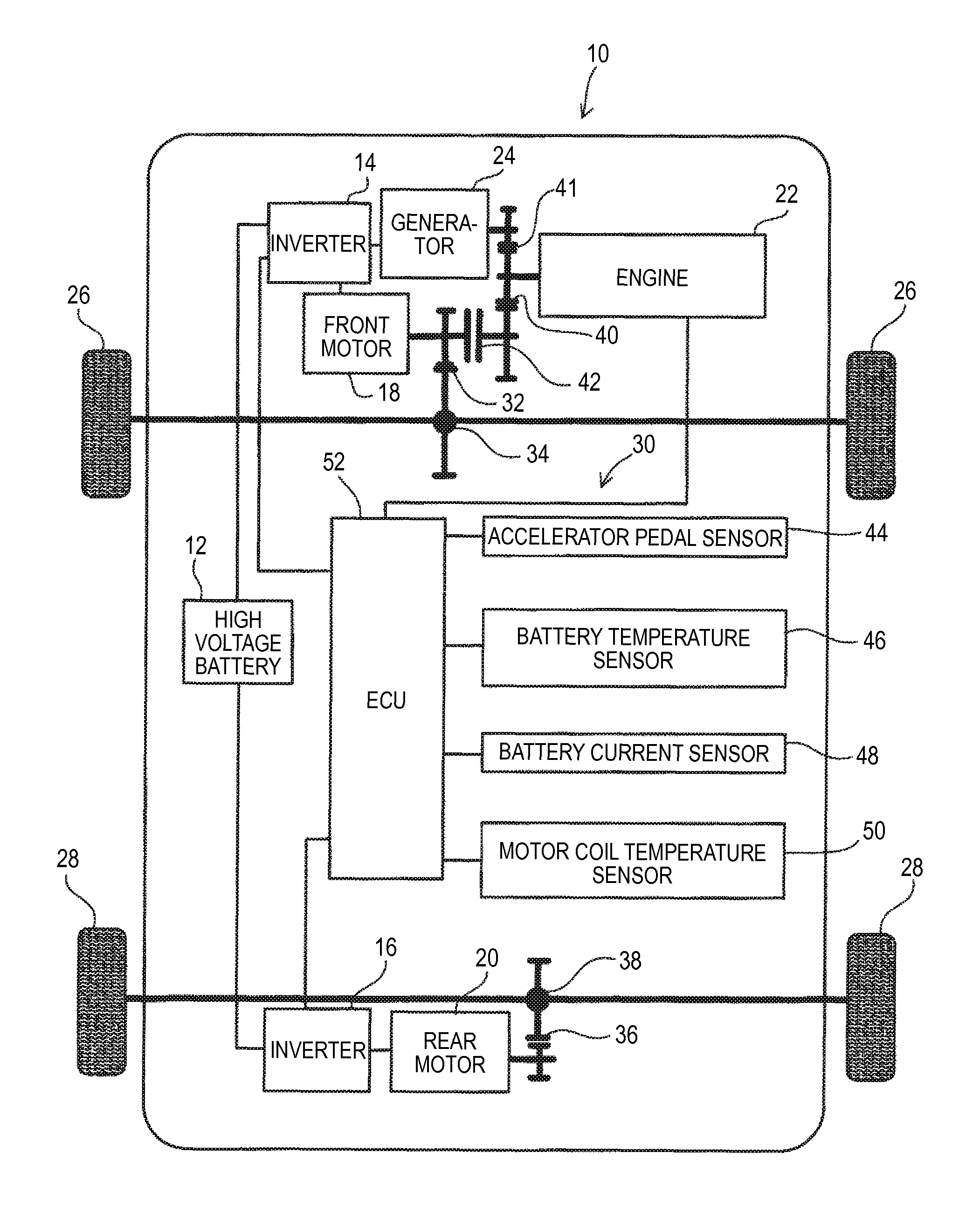
[0022]Hereinafter, an embodiment of the present invention will be described with reference to the drawings.

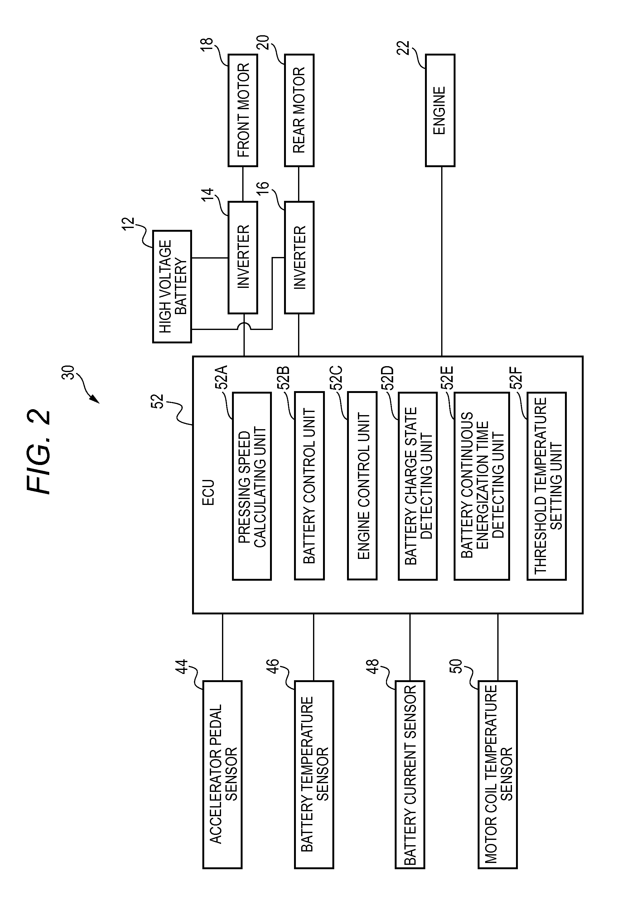
[0023]As illustrated in FIG. 1, the vehicle 10 includes: a high voltage battery 12; inverters 14 and 16; a front motor 18 serving as an electric motor; a rear motor 20 serving as an electric motor; an engine 22 serving as an internal combustion engine; a generator 24; front wheels 26; rear wheels 28; and a control apparatus 30 according to the present invention.

[0024]Accordingly, the vehicle 10 constitutes a hybrid electric vehicle on which the motors 18 and 20 and the engine 22 are installed.

[0025]The high voltage battery 12 supplies electric power to the front and rear motors 18 and 20. Further, an electric current, supplied from the high voltage battery 12 to the front and rear motors 18 and 20, will herein be referred to as a “battery current”.

[0026]Note that the high voltage battery 12 is charged with electric power supplied from, for example, a domestic commercial power s...


PUM


Abstract

A control apparatus for a hybrid electric vehicle, includes: a temperature detector configured to detect a motor temperature of the electric motor; a pressing speed detector configured to detect a pressing speed of an accelerator pedal; an electric current detector configured to detect a value of the electric current supplied to the electric motor from the battery; and an engine controller configured to allow, when the motor temperature detected by the temperature detector is equal to or lower than a threshold temperature, the engine to be started based on the pressing speed detected by the pressing speed detector, so that the generator generates the electric power, and configured to allow, when the motor temperature is higher than the threshold temperature, the engine to be started based on the value of the electric current detected by the electric current detector, so that the generator generates the electric power.

Description

BACKGROUND OF THE INVENTION[0001]The present invention relates to control apparatuses for hybrid electric vehicles.[0002]Examples of known hybrid electric vehicles include one in which an electric current is supplied to a motor from each of a battery and a generator driven by an engine, and a driving wheel is driven by driving torque outputted from the motor.[0003]For such a hybrid electric vehicle, there is proposed a technique (related art) in which when an accelerator pedal pressing speed is equal to or higher than a given value, an electric current generated by a generator by starting an engine is added to an electric current supplied from a battery, and the resulting electric current is supplied to a motor, thereby sharply increasing driving torque in response to a sudden accelerator pedal pressing operation (see Japanese Patent No. 3767103).[0004]Thus, a rush current flowing into the motor from the battery is suppressed, thereby reducing the load on the battery and ensuring re...

Claims


Application Information

Patent Timeline
IPC IPC(8): F02D29/06F02N11/08B60K6/46B60L50/16
CPCB60W20/106B60K6/448B60K6/52B60W10/06B60W10/08Y02T10/6243B60W2510/244B60W2540/106Y02T10/6286Y02T10/48Y02T10/6265B60W2510/087B60K2006/268B60W50/06B60W20/13Y02T10/40Y02T10/62
Inventor NISSATO, YUKIHIRO
Owner MITSUBISHI MOTORS CORP
Why Eureka
Try Eureka