Method for configuration and/or equipment of a vehicle cabin, in particular of an aircraft

a vehicle cabin and configuration technology, applied in the direction of program control, total factory control, instruments, etc., can solve the problems of consuming considerable computing power, consuming time and money for calculation, and consuming time for pre-engineering steps, so as to achieve efficient and quick results

Active Publication Date: 2013-03-14
SCHMIDT SCHAFFER TOBIAS +2
View PDF5 Cites 15 Cited by
  • Summary
  • Abstract
  • Description
  • Claims
  • Application Information

AI Technical Summary

Benefits of technology

[0010]The object of the invention may therefore be regarded as providing a method that overcomes the existing disadvantages and satisfies the above-mentioned requirements. In particular the method should make it possible for configuration and / or equipment of a cabin of an aircraft to be carried out efficiently and quickly, with regard to both the production and the approval or acceptance.
[0035]A dynamic zone is configured in accordance with several customer parameters as well as the parameters of the parameter zone. The elements contained therein are for example rows of seats, wall claddings and the wiring therefor, e.g. for seat-to-seat and further wiring such as the wiring for the personal service units in the ceiling etc. This wiring and positioning of the elements in the zones uses the boundary conditions from the parameter zones and thus can easily provide a basis for the construction documents for inter alia cable harnesses, the rows of seats, the PSUs (personal service units) etc.
[0036]In this case the subdivision of the cabin into parameter zones and dynamic zones offers in particular the advantage of a configuration and / or equipment that saves time and requires less computing power, as the equipment and / or the configuration does not have to be calculated for the entire cabin, but only for a predetermined zone: the dynamic zone. Because the parameter zone is configured and / or equipped with module packages, in particular with preconfigured module packages, the expenditure on computing or the expenditure of time of a given computer system is reduced, or the necessary size and power of the computer system and thus the costs thereof can be minimized.
[0040]According to a preferred embodiment of the invention, the at least one individual module parameter comprises a connection position of a hydraulic, electrical and / or mechanical connection. Thus it is possible in an advantageous manner that individual modules or the module packages are arranged in the cabin in such a way that connections arranged in the cabin can be connected to corresponding counterpart connections arranged on the individual modules or module packages. The at least one individual module parameter may preferably comprise a center of gravity and / or an aerodynamic center of gravity. Thus in an advantageous manner the individual modules or the module packages can be arranged in the cabin in such a way that an optimal secure and aerodynamic weight distribution is achieved. In particular such an optimal weight distribution enables a secure flight attitude of an aircraft.
[0044]According to yet another preferred embodiment of the invention the parameter zone is provided as an entry zone and / or the dynamic zone is provided as a passenger zone. The entry zone comprises in particular an entry region having an entrance with a cabin door, through which passengers can enter the cabin or can leave the cabin. In particular at least one galley module and / or at least one toilet module and / or at least one crew seat module, in particular one crew seat, are arranged in the entry zone. The passenger zone preferably comprises at least one passenger seat and / or at least one row of passenger seats, in particular at least one passenger seat row module. In an advantageous manner, the invention enables a user to configure or equip the parameter zone in particular from already preconfigured module packages, wherein the user does not have to know where the individual connections for joining the module packages are arranged. The parameter zone configuration, i.e. the individual module configuration, is then calculated dynamically on the basis of the individual module selection. Because only one calculation has to be carried out for the parameter zone configuration, considerable savings of computing capacity can be made.
[0052]According to a preferred embodiment a system for configuration of a cabin of an aircraft may have an input device for capturing a user input, a configuration device connected to the input device, wherein the configuration device has a processor and a memory device for storing the data of the pool of individual modules, and a display unit for displaying the desired module package (10a) and the selected module package (10b), wherein the system comprises an automatic individual module store. In this case the individual module store may for example be a fully-automated high-rack warehouse in which the individual modules are stored and after appropriate selection are called off and made available. As a result considerable savings can be made when equipping the cabins at large aircraft works with a large number of different configurable airplanes.

Problems solved by technology

Due to the immense range of possible combinations this pre-engineering step is time-consuming and expensive.
However, a disadvantage of this is that a calculation with regard to the configuration of the components in the airplane cabin must be performed for the entire airplane cabin, which makes the calculation time-consuming and requires considerable computing power.

Method used


Image

  • Method for configuration and/or equipment of a vehicle cabin, in particular of an aircraft
  • Method for configuration and/or equipment of a vehicle cabin, in particular of an aircraft
  • Method for configuration and/or equipment of a vehicle cabin, in particular of an aircraft

Examples


Embodiment Construction

[0053]The invention is explained below in greater detail on the basis of preferred embodiments with reference to the drawings. In the drawings:

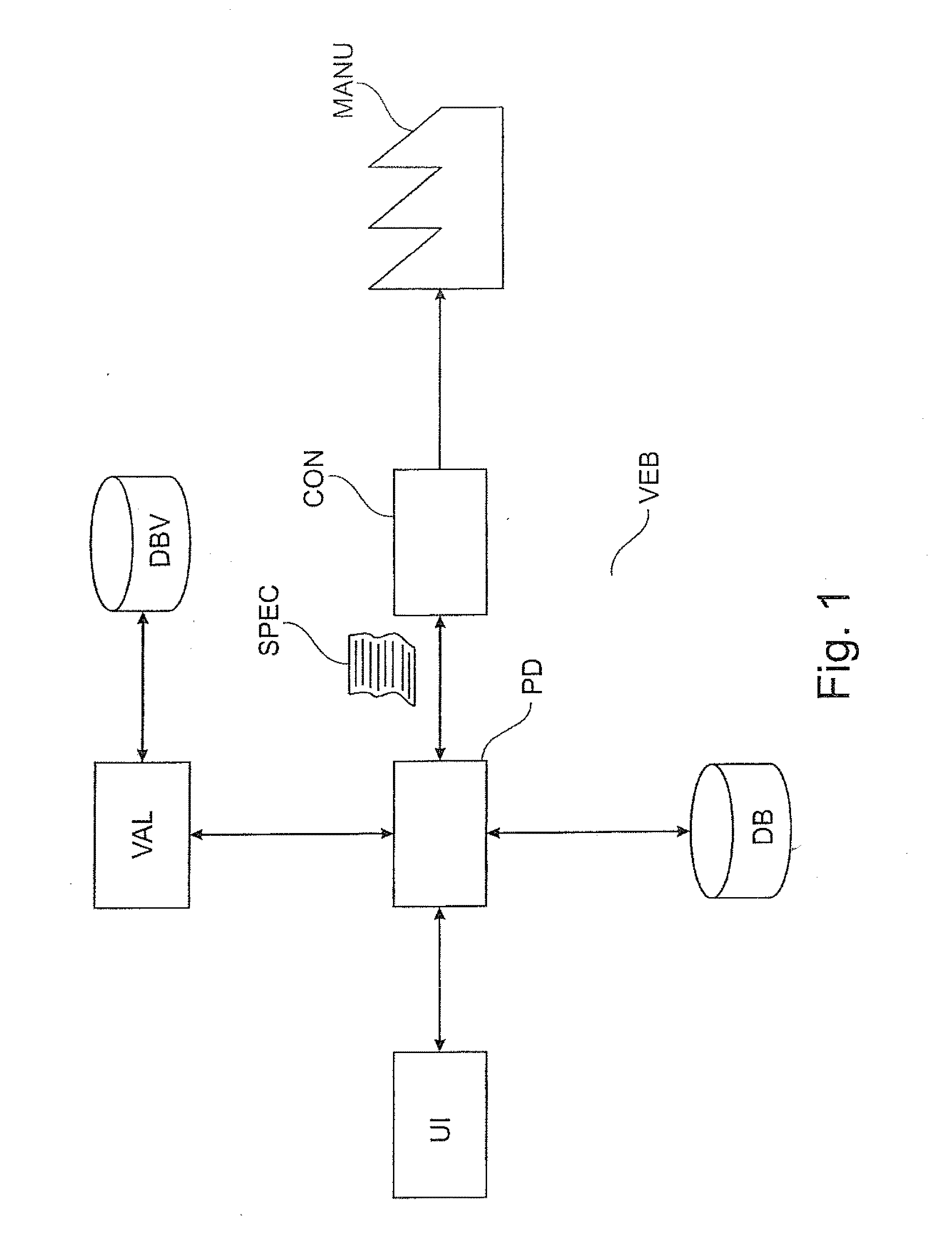
[0054]FIG. 1 shows a schematic block diagram of a production or manufacturing plant with an embodiment of the system according to the invention,

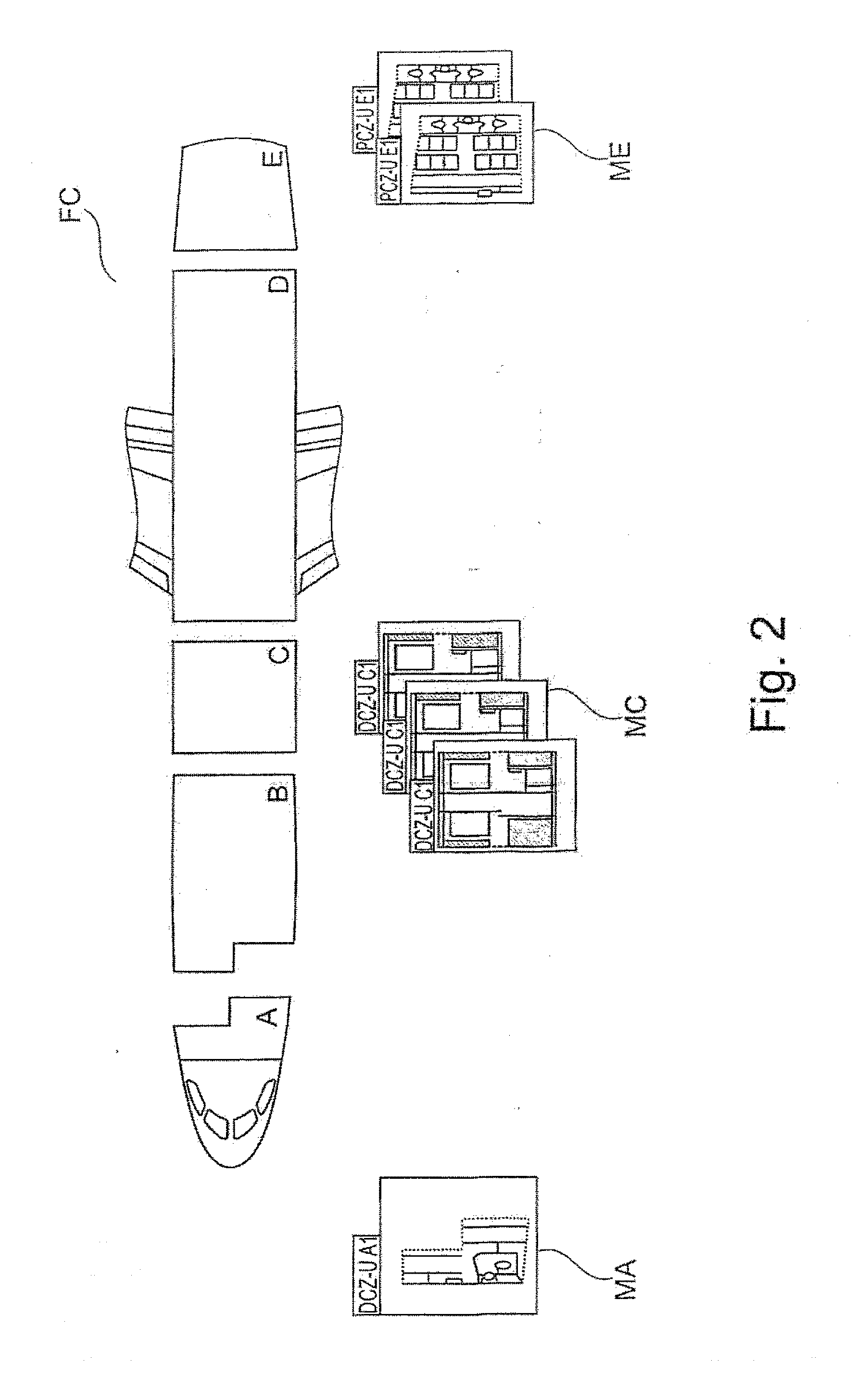
[0055]FIG. 2 shows an airplane cabin made up of modules,

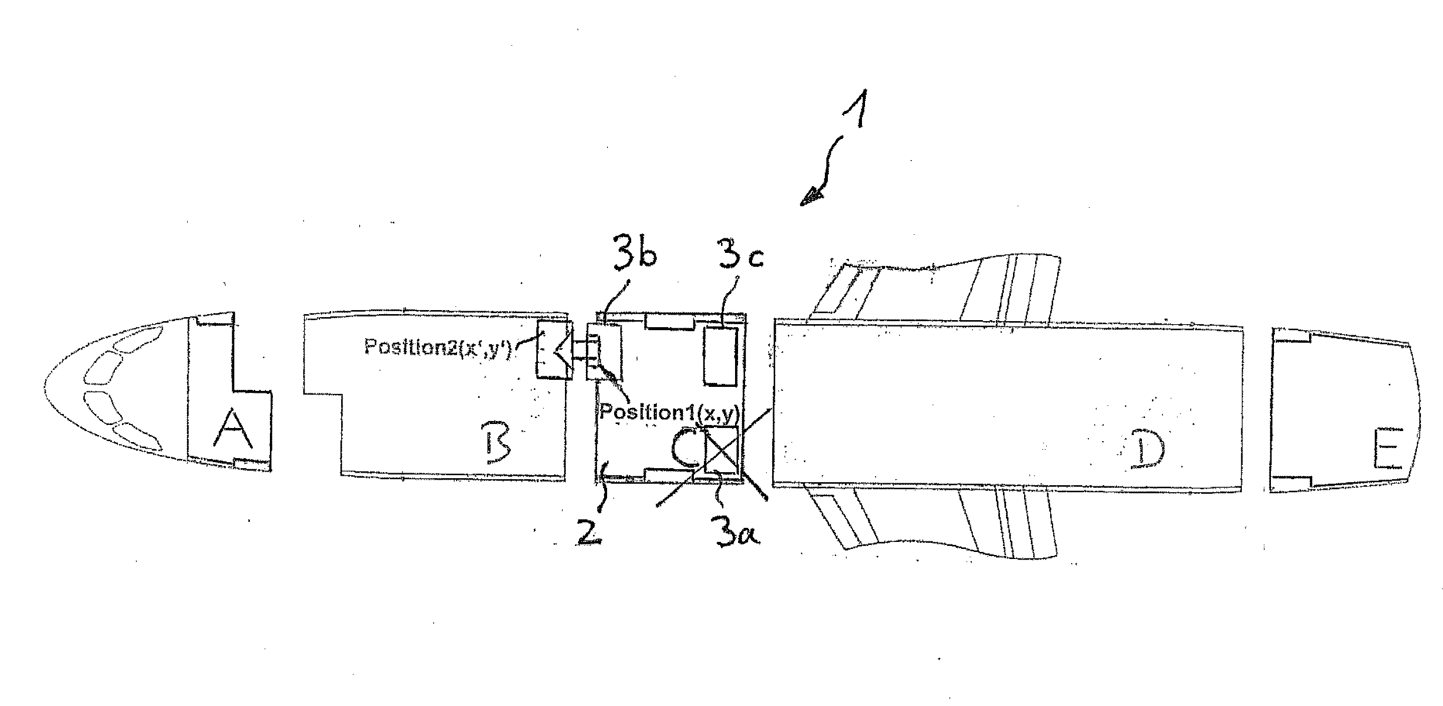
[0056]FIGS. 3a and 3b show an individual component configuration schematically,

[0057]FIG. 4 shows a schematic flow chart of an embodiment of the method according to the invention,

[0058]FIG. 5 shows an airplane cabin made up of modules,

[0059]FIG. 6 shows a module package, wherein a further individual module is added, and

[0060]FIG. 7 shows a further module package, wherein an individual module is shifted.

[0061]FIG. 1 shows schematically a system VEB, which in the illustrated embodiment is set up for automatic production of installation plans and parts lists for a cabin configuration or equipment therefor. Furthermore the system may also have an int...


PUM


Abstract

The invention relates to a method for the automatic configuration and / or equipment of a vehicle cabin (1), more particularly of an aircraft, wherein the cabin (1) is subdivided into a plurality of zones (A, B, C, D, E) and the method furthermore comprises the following steps: selection of a plurality of individual modules (11a, 11b, 11c) from a pool of individual modules, automatic connection of the selected individual modules (11a, 11b, 11c) to form a desired module package (10a), automatic calculation of a desired module package configuration value, automatic comparison of the desired module package configuration value with predefined module package configuration values which respectively correspond to a technically prevalidated module package, automatic selection of the module package (10b) whose module package configuration value deviates the least from the desired module package configuration value, arrangement of the selected module package (10b) in a zone (A, B, C, D, E) of the cabin (1). The invention furthermore relates to a system and a computer program.

Description

[0001]The invention relates to a method for automatic configuration and / or equipment of a vehicle cabin, in particular of an aircraft.BACKGROUND OF THE INVENTION[0002]In vehicles for transporting passengers there is a need to equip these with appropriate fittings.[0003]A passenger airplane for example consists of a large number of components. Many of these components may be and are ordered by the respective airlines in a certain specification, modification or configuration, i.e. they are produced according to customer requirements. There is a standard airplane that is appropriately developed and approved. Aircraft ordered by a customer are always developed and approved with regard to the standard airplane. This occurs by tracking the amendments (modifications) to the standard airplane in order to represent the corresponding customer configuration.[0004]Each airline has, in addition to certain wishes with regard to the interior fittings of the aircraft, requirements that are prescrib...

Claims


Application Information

Patent Timeline
Patent Type & Authority Applications(United States)
IPC IPC(8): G06F17/50
CPCB64F5/00G05B17/02G05B19/40931G06F2217/46G05B2219/35155G06F17/5095G05B2219/35152G06F30/15G06F2113/28Y02P90/02G06F30/00
Inventor SCHMIDT-SCHAFFER, TOBIASBECKER, BENJAMINSEIFERT, ULRICH
Owner SCHMIDT SCHAFFER TOBIAS
Why Eureka
Try Eureka