Solder cap bump in semiconductor package and method of manufacturing the same

a semiconductor and bump technology, applied in the field of semiconductor package, can solve the problems of difficult control of the volume of the solder cap during the electroplating operation, the inability to use pure tin (sn) or sn (tin)/ag (silver) alloy in the electroplating operation, and the inability to perform electroplating for other different solder alloys, etc., to achieve easy and precise control, enhance the reliability of the interconnection between bumps, and improve the height uniform

Active Publication Date: 2013-03-21
CHIPMOS TECH INC
View PDF24 Cites 6 Cited by
  • Summary
  • Abstract
  • Description
  • Claims
  • Application Information

AI Technical Summary

Benefits of technology

[0007]It is an object of the present invention to provide a bump for a semiconductor package and a manufacturing process thereof where the size (volume) of a solder cap of th...

Problems solved by technology

One disadvantage of conventional bump with solder cap formation is that only pure tin (Sn) or Sn (tin)/Ag (silver) alloy could be used in the electroplating operation.
Practically, it is very difficult to perform electroplating for other different solder alloy...

Method used


Image

  • Solder cap bump in semiconductor package and method of manufacturing the same
  • Solder cap bump in semiconductor package and method of manufacturing the same
  • Solder cap bump in semiconductor package and method of manufacturing the same

Examples


Embodiment Construction

[0022]The detailed description set forth below is intended as a description of the presently exemplary device provided in accordance with aspects of the present invention and is not intended to represent the only forms in which the present invention may be prepared or utilized. It is to be understood, rather, that the same or equivalent functions and components may be accomplished by different embodiments that are also intended to be encompassed within the spirit and scope of the invention.

[0023]Unless defined otherwise, all technical and scientific terms used herein have the same meaning as commonly understood to one of ordinary skill in the art to which this invention belongs. Although any methods, devices and materials similar or equivalent to those described can be used in the practice or testing of the invention, the exemplary methods, devices and materials are now described.

[0024]All publications mentioned are incorporated by reference for the purpose of describing and disclos...


PUM


Abstract

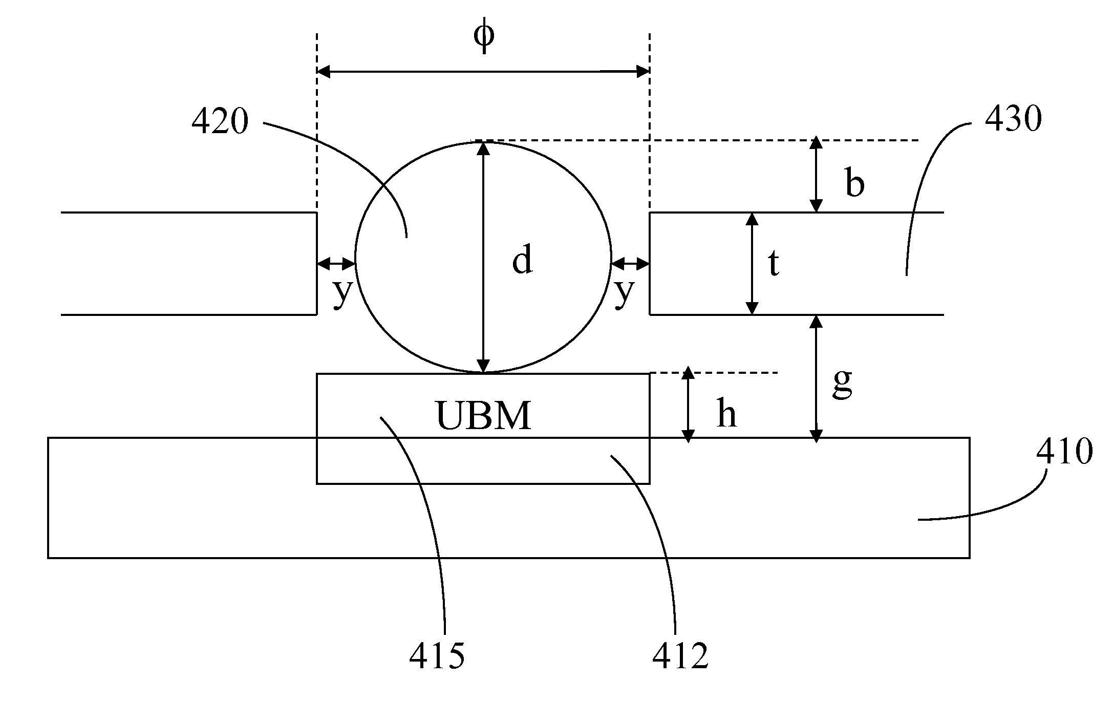
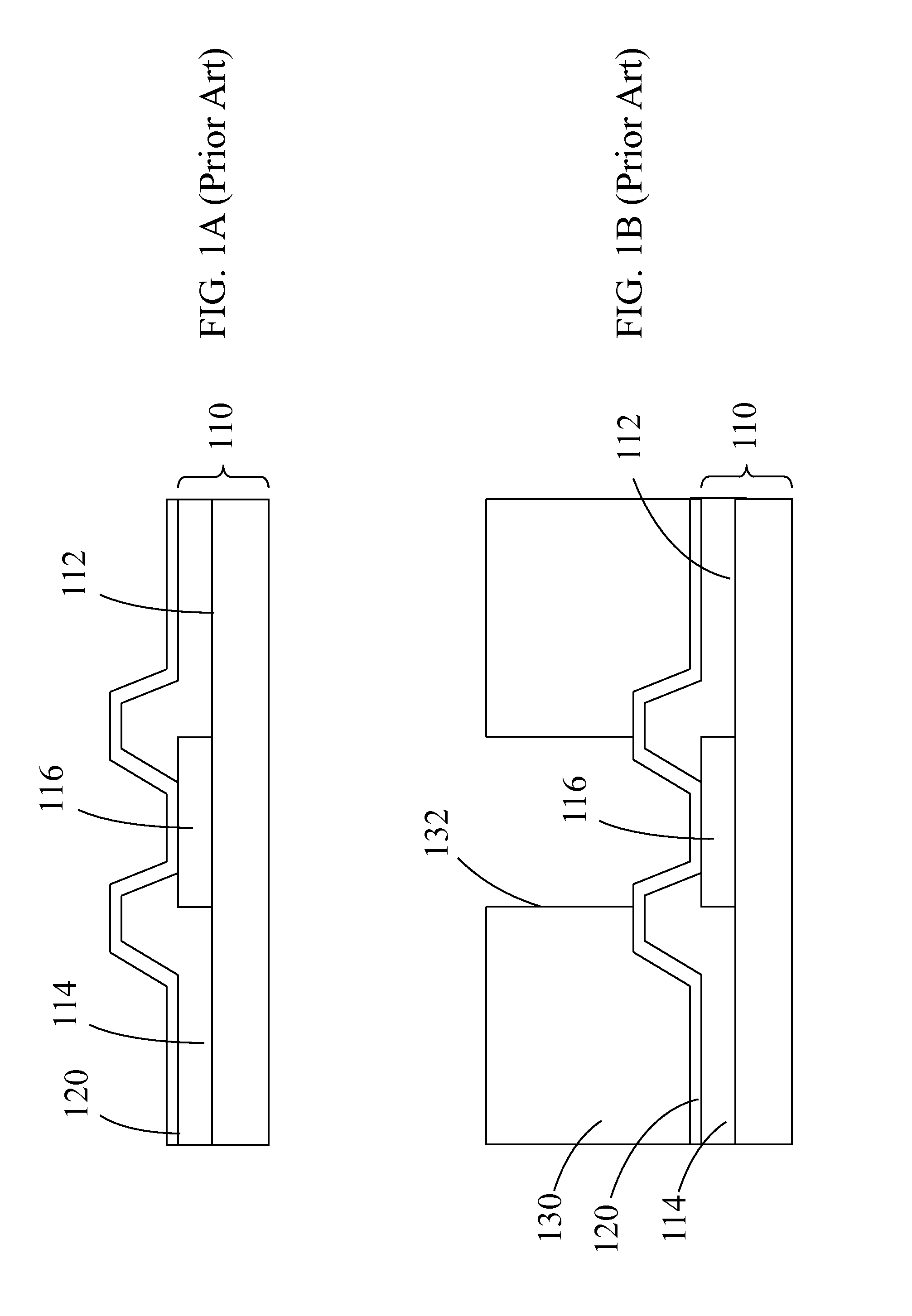
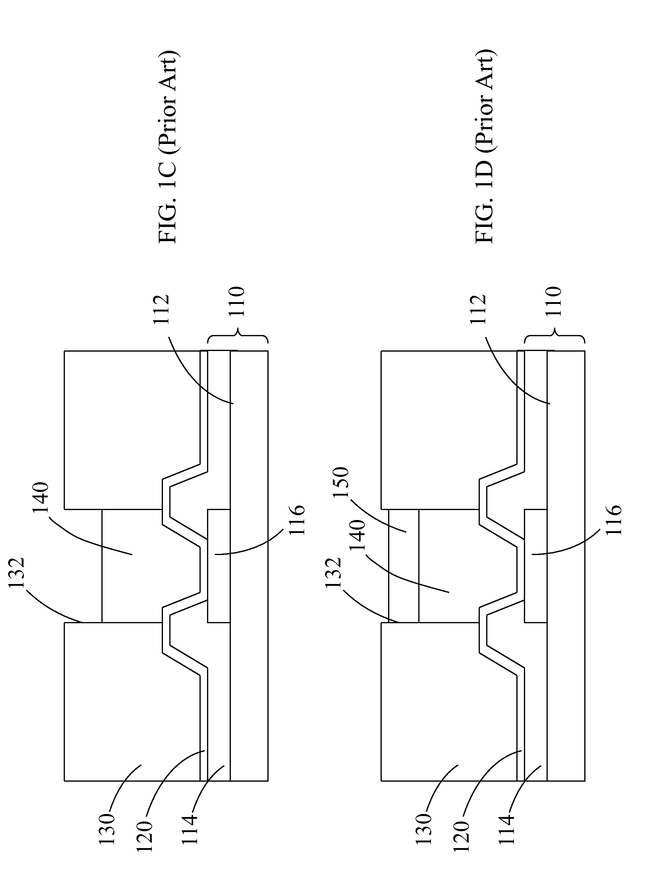
A semiconductor package with improved height uniformity of solder cap bumps therein is disclosed. In one embodiment, the semiconductor package includes a semiconductor substrate comprising a plurality of pads spacedly disposed on a top surface of the substrate, and a passivation layer formed on top of the pads, wherein a plurality of pad openings are created to expose at least a portion of the pads; a plurality of solder cap bumps formed at the pad openings of the passivation layer; and a carrier substrate having a plurality of bond pads electrically connected to the solder caps of the solder cap bumps on the semiconductor substrate. The solder cap bump includes a solder cap on top of a conductive pillar, and a patternable layer can be coated and patterned on a top surface of the conductive pillar to define an area for the solder ball to be deposited. The deposited solder ball can be reflowed to form the solder cap.

Description

FIELD OF THE INVENTION[0001]The present invention is related to a semiconductor package, and more particularly to a method for forming solder cap bumps with improved height uniformity to enhance reliability of the interconnection between a solder cap bump and a pad in the semiconductor package.BACKGROUND OF THE INVENTION[0002]With the remarkable advances in semiconductor technologies, the electronics industry has been through a very rapid revolution from thick to thin films and to ever increasing miniaturization. Semiconductor packaging, which is the science of establishing interconnections with the semiconductor devices to form circuits, has been developed concurrently with the rapid advances in the semiconductor and electronics industries. The main purpose of packaging is to ensure that the semiconductor devices and interconnections are packaged efficiently and reliably.[0003]As miniaturization and high performance are demanded in electronic products (such as cell phones, laptops,...

Claims


Application Information

Patent Timeline
IPC IPC(8): H01L23/488H01L21/56H01L21/283
CPCH01L23/3114H01L2224/13541H01L2224/11005H01L24/11H01L24/13H01L24/16H01L24/81H01L2224/034H01L2224/036H01L2224/056H01L2224/11334H01L2224/11462H01L2224/11849H01L2224/13022H01L2224/13082H01L2224/13144H01L2224/13147H01L2224/81191H01L2224/814H01L2224/83104H01L2224/111H01L2224/05572H01L23/3121H01L2224/16237H01L2224/73204H01L2224/0401H01L2924/00014H01L2924/014H01L2924/00012H01L2924/206H01L2224/05552H01L2224/1308
Inventor SHEN, GENG-SHIN
Owner CHIPMOS TECH INC
Why Eureka
Try Eureka