Control system for rotating shaft

a control system and rotating shaft technology, applied in the direction of electric controllers, controllers with particular characteristics, instruments, etc., can solve problems such as unfree, achieve the effects of reducing the influence of frictional force, removing error components, and improving stability

Active Publication Date: 2013-03-21
HANWHA AEROSPACE CO LTD
View PDF3 Cites 10 Cited by
  • Summary
  • Abstract
  • Description
  • Claims
  • Application Information

AI Technical Summary

Benefits of technology

[0009]One or more exemplary embodiments provide a rotating element control system having an improved degree of accuracy in terms of stability by reducing influence of a frictional force acting between mechanical elements.
[0010]One or more exemplary embodiments also provide a rotating element control system having a function to effectively remove an error component generated by a frictional force acting between mechanical elements.

Problems solved by technology

However, since the control system considers only a frictional force generated from inside the RCWS, an amount of a motion of a vehicle equipped with the RCWS and driving of a rotating shaft according to a speed command instructed by an operator are not free from influence of various frictional disturbances generated by mechanical constituent elements of the RCWS.
However, it is understood that one or more exemplary embodiment are not required to overcome the disadvantages described above, and may not overcome any of the problems described above.

Method used


Image

  • Control system for rotating shaft
  • Control system for rotating shaft
  • Control system for rotating shaft

Examples


Embodiment Construction

[0026]Hereinafter, exemplary embodiments will be described in detail with reference to the attached drawings. Like reference numerals in the drawings denote like elements.

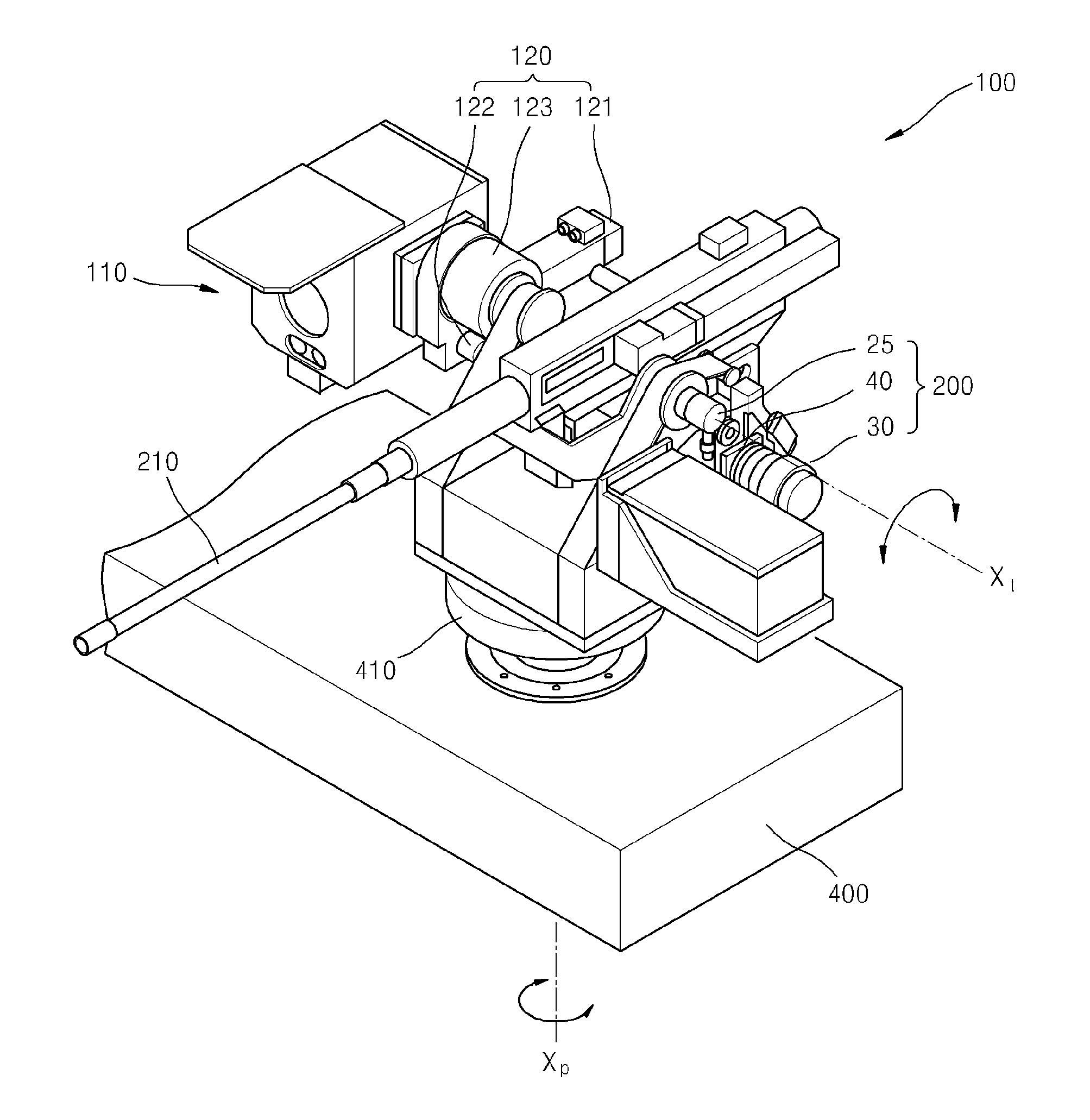
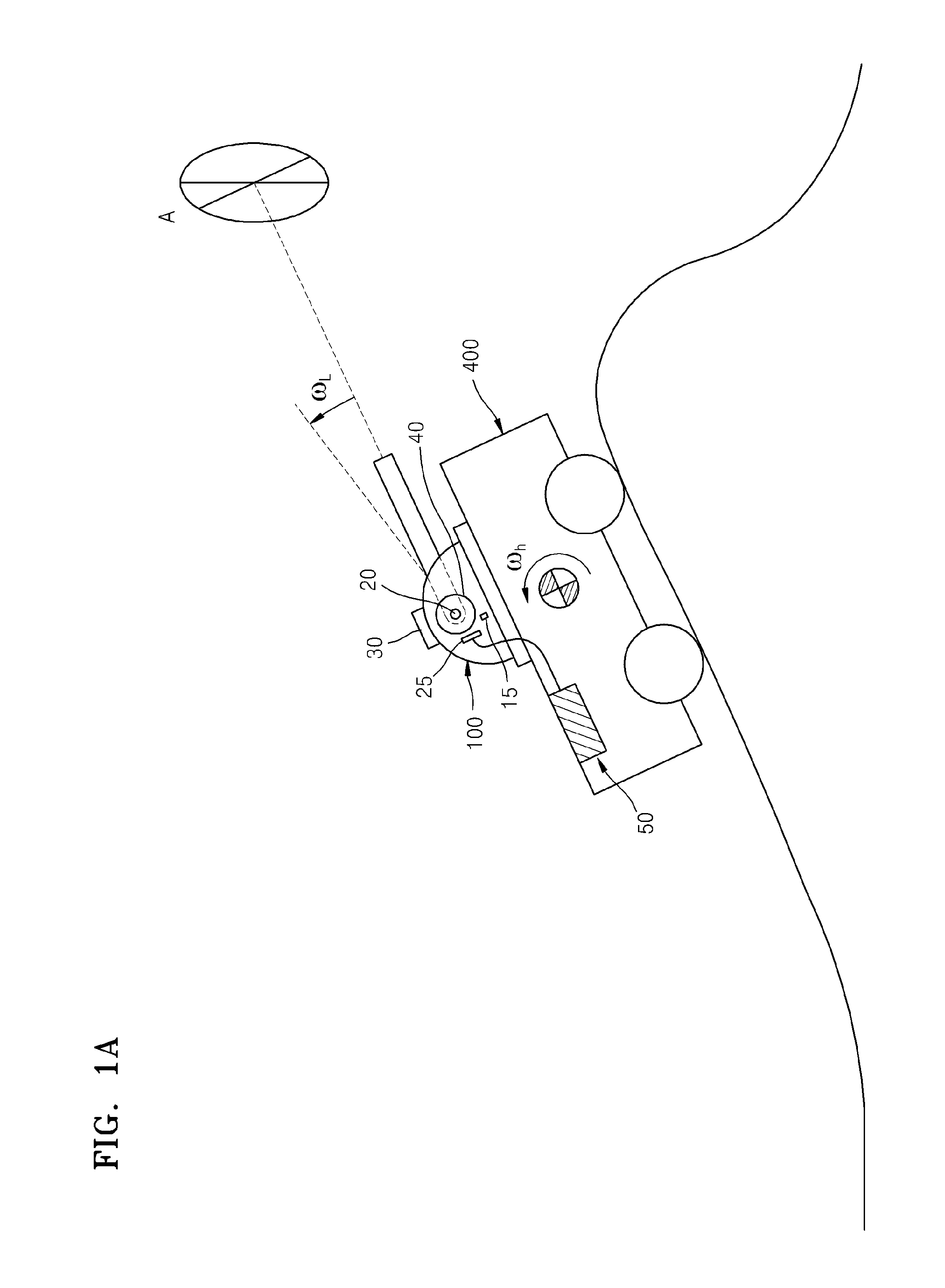
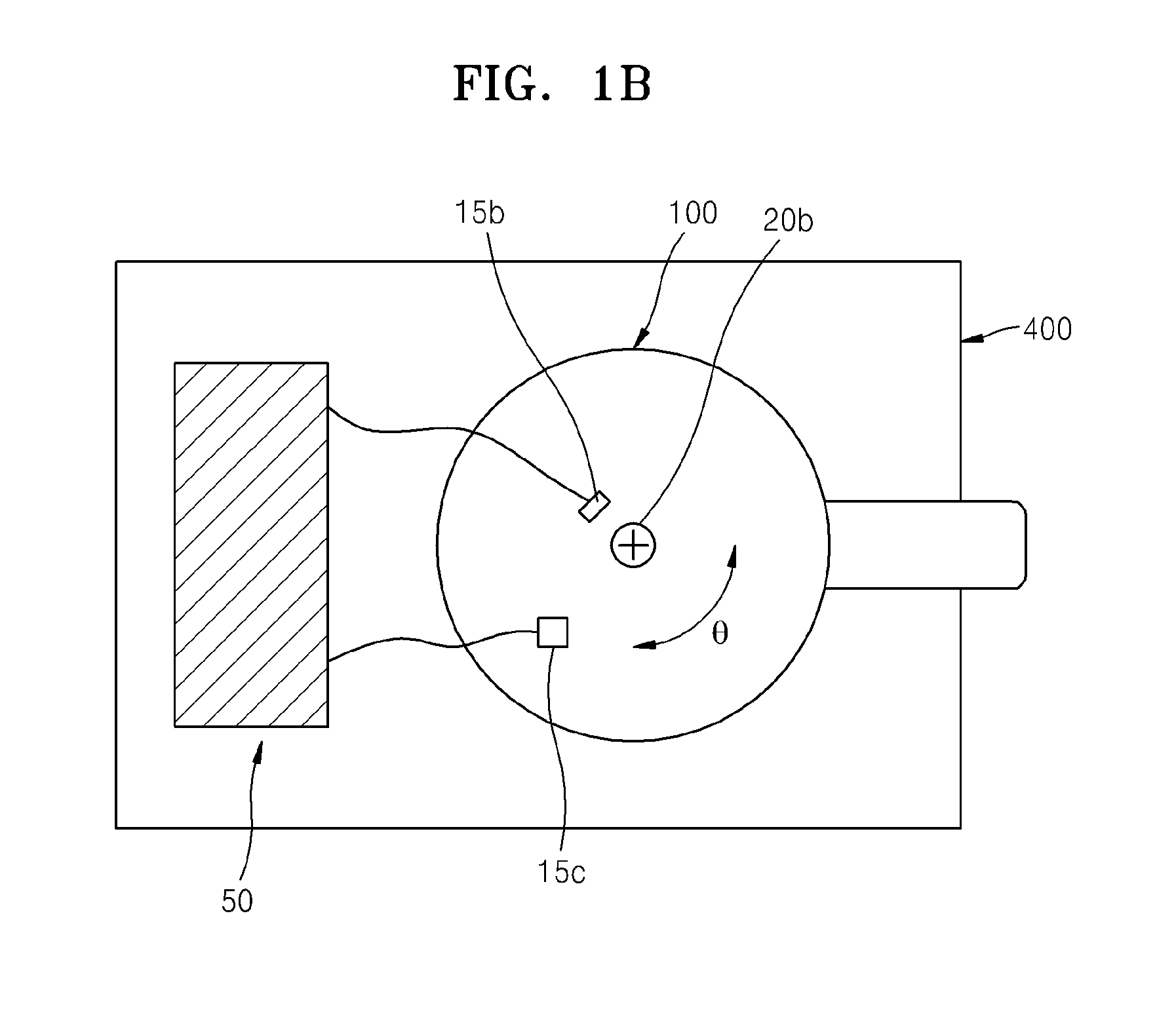
[0027]FIG. 1A is a conceptual view schematically illustrating an operational state of a remote control weapon station (RCWS) having a rotating shaft control system according to an embodiment. Referring to FIG. 1A, the rotating shaft control system according to the present embodiment is used to control driving of an RCWS 100 and includes a rotating shaft 20 rotatably installed on a main body 400, a first sensing unit 15 for sensing a rotational speed of the main body 400, a driving unit 30 for driving the rotating shaft 20, a second sensing unit 25 for sensing a rotational speed of the rotating shaft 20, and a control unit 50. A transfer unit 40 for transferring a driving force is arranged between the rotating shaft 20 and the driving unit 30.

[0028]Although in FIG. 1A the main body 400 where the RCWS 100 is installe...


PUM


Abstract

A rotating element control system includes a rotating element rotatably disposed on a main body, a first sensing unit which senses a rotational speed of the main body, a driving unit which drives the rotating element, a second sensing unit which senses a rotational speed of the rotating element, a torque compensation unit which generates a first compensation signal within a first range and a second compensation signal within a second range, and a stabilization control unit which controls the driving unit based on the first and second compensation signals and a difference between a speed of a command to drive the rotating element and the rotational speed of the rotating element.

Description

CROSS-REFERENCE TO RELATED PATENT APPLICATIONS[0001]This application claims priority from Korean Patent Application No. 10-2011-0094278, filed on Sep. 19, 2011, in the Korean Intellectual Property Office, the disclosure of which is incorporated herein by reference in its entirety.BACKGROUND[0002]1. Field[0003]Apparatuses and methods consistent with exemplary embodiments relate to a rotating shaft control system, and more particularly, to a rotating shaft control system having an improved degree of accuracy in terms of stability by reducing influence of a frictional force acting between mechanical elements.[0004]2. Description of the Related Art[0005]A remote control weapon station (RCWS) is a system that enables precise shooting on a target by adjusting a weapon from a remote place to prevent a gunner from being exposed to the outside when performing a battle operation at a near or far distance. The RCWS is mounted on a variety of vehicles such as unmanned vehicles, unmanned armored...

Claims


Application Information

Patent Timeline
Patent Type & Authority Applications(United States)
IPC IPC(8): G05B11/36
CPCG05B11/36
Inventor LIM, YONG-SEOBCHOI, SEUNG-JIN
Owner HANWHA AEROSPACE CO LTD
Why Eureka
Try Eureka