Attenuating antenna switch and communication device

a technology of communication device and antenna switch, which is applied in the direction of climate sustainability, sustainable buildings, high-level techniques, etc., can solve the problems of increasing the transmission power cannot be sufficiently decreased, and the scale and power consumption of the rfic are large, so as to reduce the dynamic range of the rfic, reduce the scale and power consumption of the rfic, and reduce the effect of the rfi

Active Publication Date: 2013-03-21
RENESAS ELECTRONICS CORP
View PDF3 Cites 37 Cited by
  • Summary
  • Abstract
  • Description
  • Claims
  • Application Information

AI Technical Summary

Benefits of technology

[0018]That is, in the present invention, by varying the passage loss of the antenna switch, the high frequency signal is attenuated. Consequently, the dynamic r

Problems solved by technology

The inventors of the present invention found out that the communication device has a problem in that the scale and power consumption of an RFIC is large.
Concretely, at the time of adjusting transmission power, the transmission power cannot be sufficiently decreased by the gain adjustment of the HPA.
Therefore, a wide dynamic range of about 60 dB to 70 dB is requested for the RFIC, and it causes increase in the scale and

Method used


Image

  • Attenuating antenna switch and communication device
  • Attenuating antenna switch and communication device
  • Attenuating antenna switch and communication device

Examples


first embodiment

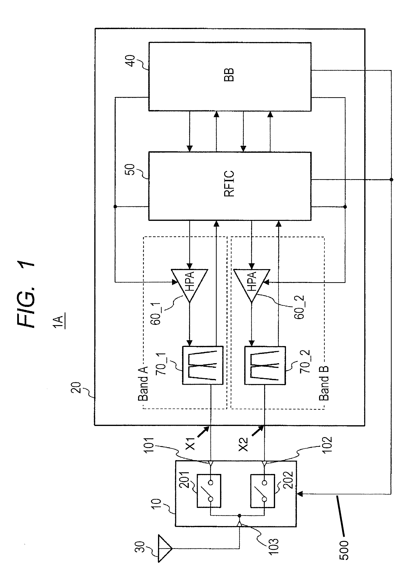
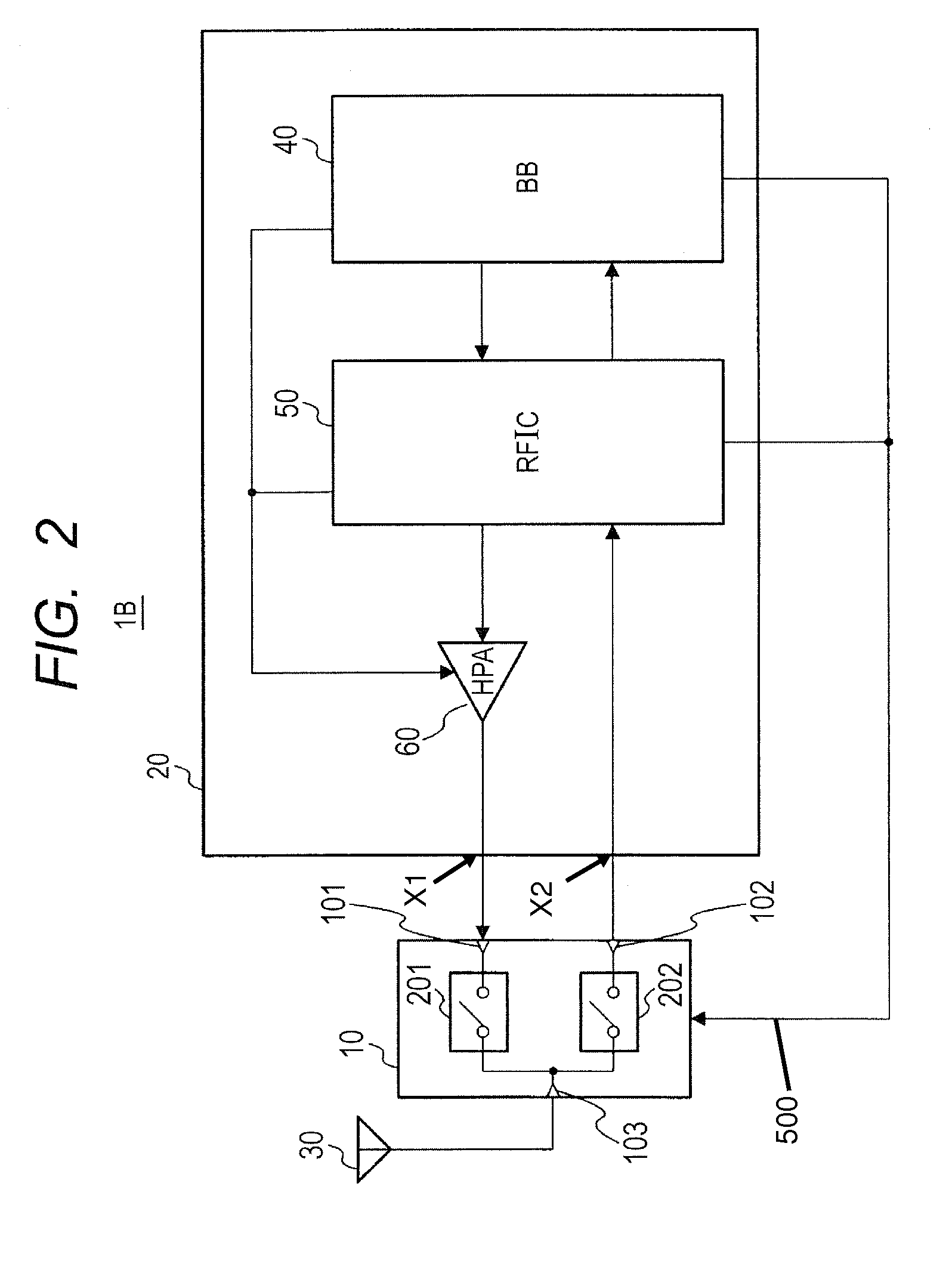
[0037]As shown in FIG. 1, a communication device 1A of a first embodiment employs, as a communication system, the FDD (Frequency Division Duplex) method such as WCDMA (Wideband Code Division Multiple Access). The communication device 1A has an attenuating antenna switch 10 (“antenna switch”) according to the embodiment and a transmission / reception circuit 20.

[0038]The antenna switch 10 includes two (respective first and second) signal terminals 101 and 102, an antenna terminal 103 for coupling an antenna 30, and two (respective first and second) switches 201 and 202.

[0039]The switch 201 switches between a first state where a high frequency signal is propagated between the signal terminal 101 and the antenna terminal 103 (hereinbelow, called a propagation state) and a second state where the high frequency signal is interrupted (hereinbelow, called an interruption state). The switch 202 similarly switches between the propagation state and the interruption state between the signal term...

second embodiment

[0082]A communication device of a second embodiment can be configured in a manner similar to that of the first embodiment. The second embodiment is different from the first embodiment with respect to the point that the antenna switch is configured as shown in FIG. 9.

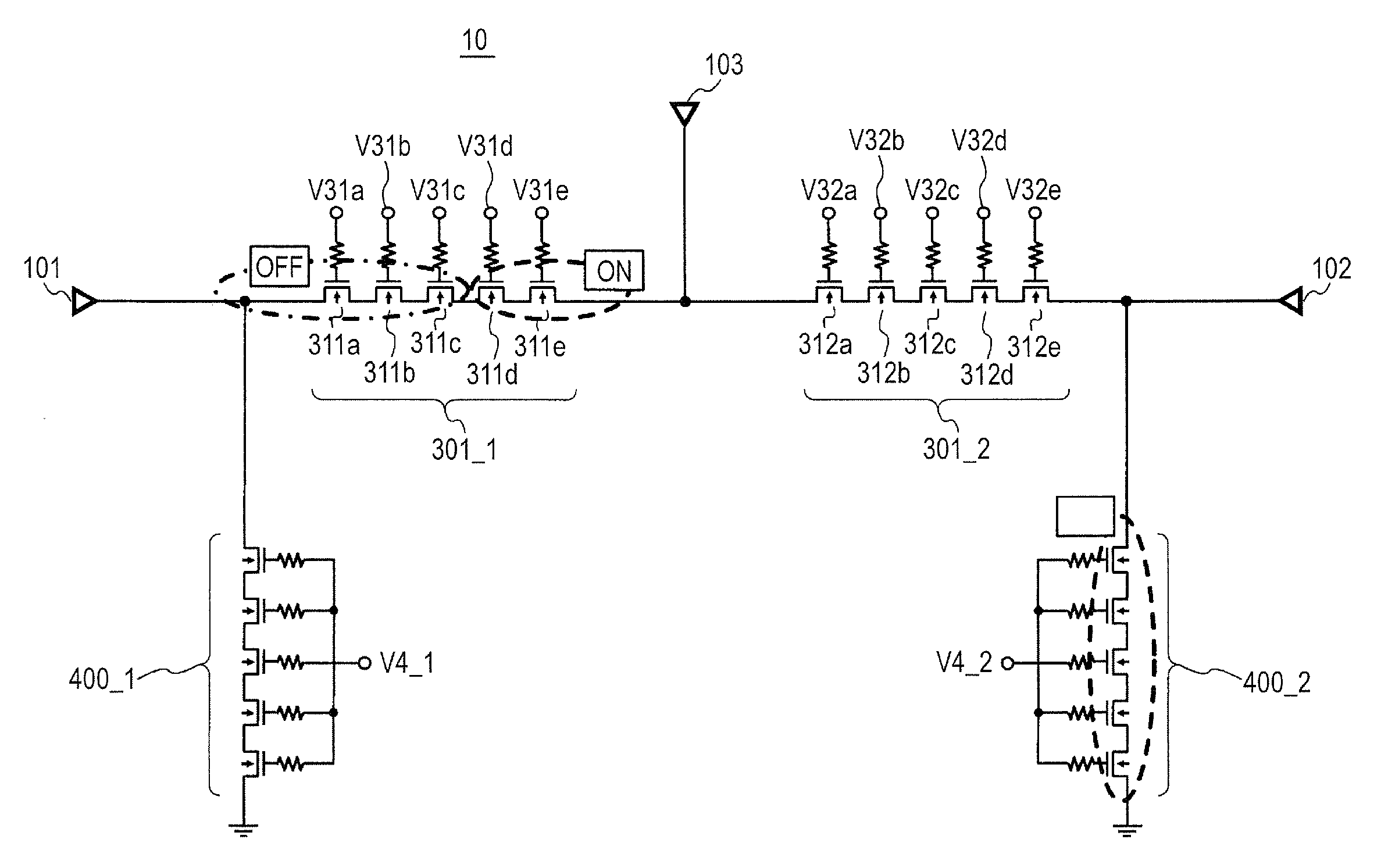
[0083]Concretely, as shown in FIG. 9, the first switch 201 in an antenna switch 10A of the second embodiment is provided with a first FET series block 300_1 in place of the series first FET block 301_1 shown in FIG. 3. The first FET series block 300_1 is configured by a plurality of FETs whose source and drain paths are coupled in series between the first signal terminal 101 and the antenna terminal 103. To the FETs in the first FET series block 300_1, common first series control voltage V3_1 is applied from the RFIC 50 or the BB circuit 40 via gate resistors.

[0084]The switch 202 is provided with a series block 300_2 in place of the series block 301_2 shown in FIG. 3. The second FET series block 300_2 is made by a plural...

third embodiment

[0090]A communication device of a third embodiment can be configured in a manner similar to that of the first embodiment. The third embodiment is different from the first and second embodiments with respect to the point that the antenna switch is configured as shown in FIG. 11.

[0091]Concretely, as shown in FIG. 11, the first switch 201 in an antenna switch 10B of the third embodiment includes the first FET series block 300_1 like in FIG. 9. The first switch 201 is provided with a first FET shunt block 402_1 in place of the first FET shunt block 400_1 shown in each of FIGS. 3 and 9. For example, the first FET shunt block 402_1 is made by five FETs 421a to 421e whose source and drain paths are coupled in series between the ground point and a coupling point (first node) between the signal terminal 101 and the first FET series block 300_1. To the FETs 421a, 421b, 421c, 421d, and 421e, individual control voltages V41a, V41b, V41c, V41d, and V41e are applied, respectively, from the RFIC 5...


PUM


Abstract

An attenuating antenna switch may be used to suppress increase in the scale and power consumption of an RFIC. The antenna switch has a first terminal, a second terminal, and an antenna terminal coupled to the first and second terminals and configured to be connected to an antenna. The first switch switches between a first state in which a high frequency signal is propagated between the first terminal and the antenna terminal, and a second state in which the high frequency signal is interrupted. A second switch switches between the first and second states between the second terminal and the antenna terminal. The first and second switches are controlled in a mutually exclusive manner such that only one of the two switches can be in the first state at any given time. When in the first state, each switch adjusts an attenuation amount of the high frequency signal.

Description

CROSS-REFERENCE TO RELATED APPLICATIONS[0001]The disclosure of Japanese Patent Application No. 2011-203480 filed on Sep. 16, 2011 including the specification, drawings and abstract is incorporated herein by reference in its entirety.BACKGROUND[0002]The present invention relates to an antenna switch and a communication device and, more particularly, to a technique of adjusting power of a high frequency signal by means of an attenuating antenna switch configured to attenuate a signal in a controlled manner.[0003]A communication device such as a cellular phone performs stationary communication with a base station as a relay device at the time of radio communication between communication devices. A communicatable range of one base station is called a cell. In one cell, a communication device adjusts transmission power of a high frequency signal and reception sensitivity in accordance with distance to the base station.[0004]Generally, the transmission power has to be adjusted in the rang...

Claims


Application Information

Patent Timeline
IPC IPC(8): H01P1/15H04W88/02H01P1/10H04B1/44
CPCY02B60/50H04B1/109Y02D30/70
Inventor GOTO, SATOSHIHORI, KAZUAKISAKURAI, SATOSHI
Owner RENESAS ELECTRONICS CORP
Why Eureka
Try Eureka