Vehicle damping control device

a control device and vehicle technology, applied in the direction of braking systems, cycle equipment, instruments, etc., can solve the problems of output decrease of correction torque, and achieve the effects of preventing prolonging time, restrainting hunting occurrence, and preventing reoccurren

Active Publication Date: 2013-03-21
NISSAN MOTOR CO LTD
View PDF1 Cites 5 Cited by
  • Summary
  • Abstract
  • Description
  • Claims
  • Application Information

AI Technical Summary

Benefits of technology

[0007]Thus, the vibration damping control apparatus restrains the occurrence of hunting with output decrease of the correction torque against hunting generated temporarily by an external factor such as a rough road. The vibration damping control apparatus is configured to cancel the output decrease when it is judged that the hunting is not generated in the calculated correction torque during the output decrease. Therefore, the vibration damping control apparatus can resume the control promptly after passage through a rough road, and thereby prevent prolongation of the time during which the vibration damping control is inoperative. Additionally, when the hunting is generated continuously, the vibration damping control apparatus outputs the hunting time correction torque command continuously. Therefore, the vibration damping control apparatus can restrain reoccurrence of the hunting.

Problems solved by technology

Thus, the vibration damping control apparatus restrains the occurrence of hunting with output decrease of the correction torque against hunting generated temporarily by an external factor such as a rough road.

Method used


Image

  • Vehicle damping control device
  • Vehicle damping control device
  • Vehicle damping control device

Examples


embodiment 1

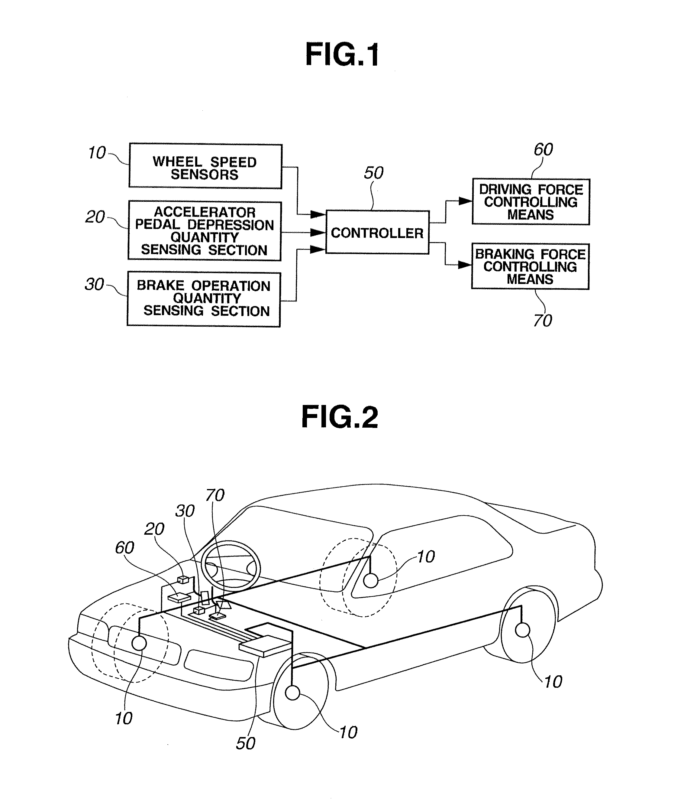
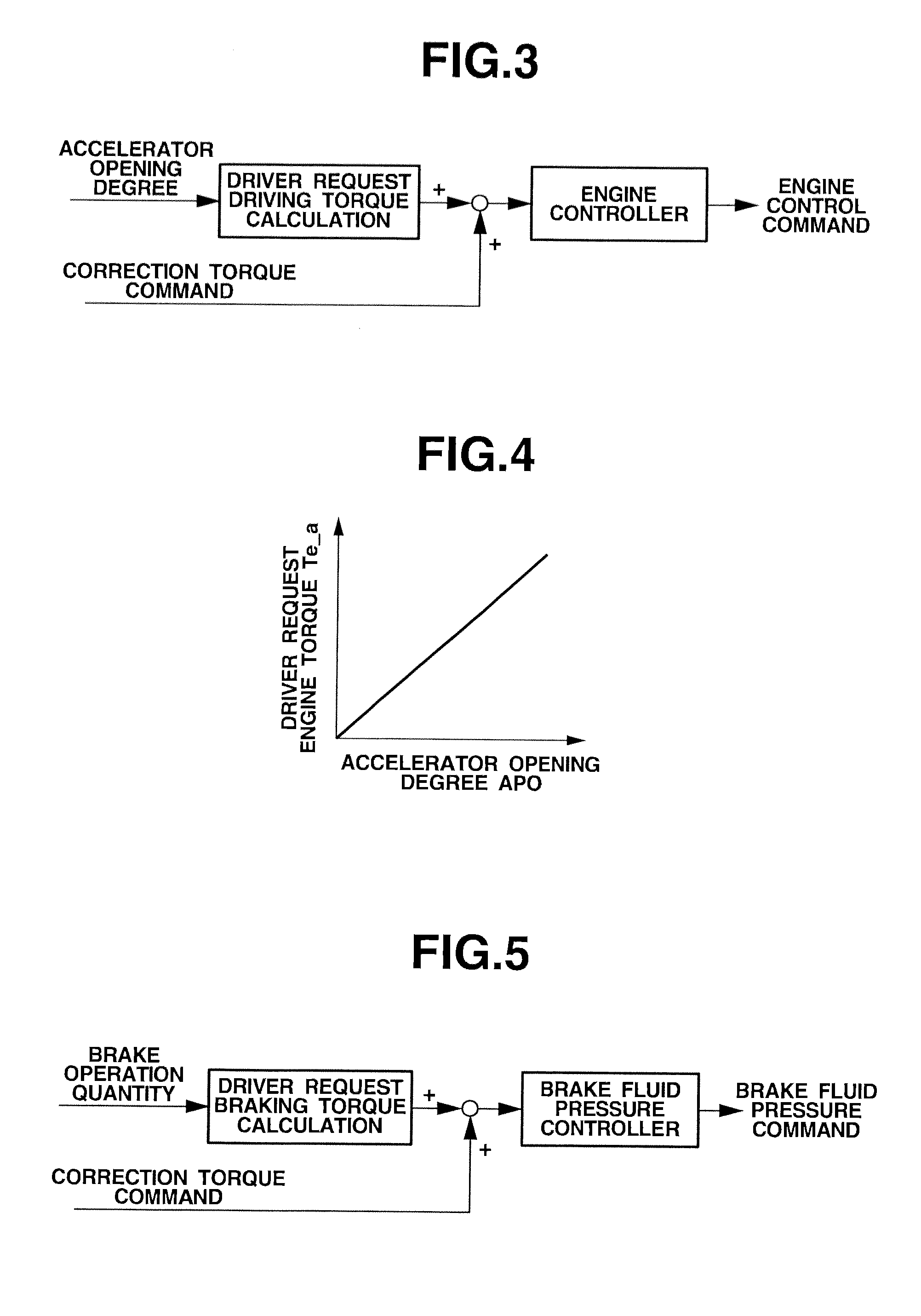
[0034]FIG. 1 is a system view showing the structure of a vibration damping or suppressing apparatus according to an embodiment 1. FIG. 2 is a structure view showing a vehicle equipped with the vibration damping apparatus. First, explanation is directed to the structure of the vibration damping apparatus. Wheel speed sensors 10 sense the wheels speeds of respective wheels of the vehicle from the rpms of the respective wheels. An accelerator pedal depression quantity sensing section 20 senses an accelerator opening degree APO representing the depression quantity of an accelerator pedal by the driver. A brake operation quantity sensing section 30 senses a brake operation quantity S_b by the driver (such as a brake pedal stroke quantity or a depressing force on a brake pedal).

[0035]A controller 50 delivers control signals to a driving force controlling means or device 60 and a braking force controlling means or device 70 which are an actuator of the vibration suppressing apparatus, in a...

embodiment 2

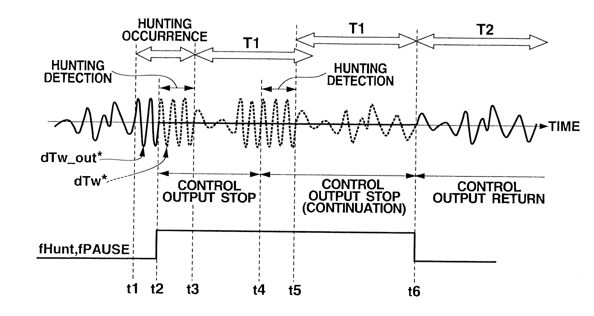
[0143]Following is explanation on a second embodiment of the present invention. Since the basic construction is the same as that of the first embodiment, the explanation is directed only to points different from the first embodiment. FIG. 20 shows, in the form of a flowchart, a process, according to the second embodiment, of setting the output mode. A hunting detecting process at a step 620 is basically the same as that of the first embodiment, and hence explanation is omitted. The hunting monitoring time period Cycle_Timelmt set in the hunting monitoring timer tHunt_Cycle used in the hunting detecting process of the second embodiment is set shorter than the hunting monitoring time period Cycle_Timelmt according to the first embodiment. With this setting, the control system can detect hunting at the time of detection of a brake operation, as hunting attributable to the vehicle's side quickly, and thereby reduce the number of occurrences of hunting. The hunting at the time of detecti...

embodiment 3

[0159]Following is explanation on a third embodiment of the present invention. Since the basic construction is the same as that of the second embodiment, the explanation is directed only to points different from the preceding embodiment. FIG. 24 shows, in the form of a flowchart, an output mode setting process according to the third embodiment. Since steps S620 and S660 are the same as those of the second embodiment, the explanation is directed only to a different step S670′. The hunting monitoring time period Cycle_Timelmt set in the hunting monitoring timer tHunt_Cycle used in the hunting detecting process of the second embodiment is set shorter than the hunting monitoring time period Cycle_Timelmt according to the first embodiment. With this setting according to the third embodiment, the control system can detect hunting at the time of detection of shimmy, as hunting attributable to the vehicle's side, quickly, and thereby reduce the number of occurrences of hunting. The hunting ...


PUM


Abstract

A correction torque command is outputted to a driving/braking torque producing means in accordance with a correction torque to suppress vehicle body sprung vibration. When a state of the correction torque amplitude being greater than or equal to a predetermined amplitude continues for a predetermined time, a control apparatus outputs a hunting time correction torque command smaller than a normal time correction toque command. When a state of the correction torque amplitude being smaller than or equal to the predetermined amplitude continues for a first predetermined time, the control apparatus returns the output of correction torque command from the hunting time correction torque command to the normal time correction torque command. The control apparatus continues the output of the hunting time correction torque command if the state in which the correction torque amplitude exceeds the predetermined amplitude continues for the predetermined time, before the expiration of the first time period.

Description

TECHNICAL FIELD[0001]The present invention relates to a vibration damping or vibration suppressing control device or apparatus for suppressing or restraining vibrations produced in a vehicle.BACKGROUND ART[0002]A patent document 1 discloses a vibration suppressing technique to calculate a vibration suppressing torque for suppressing sprung vibrations by using, as input variables, a driving torque and a wheel speed, and to decrease a control gain when a vibration amplitude of the vibration suppressing torque continues to be greater than or equal to a predetermined amplitude for a predetermined time length (referred to as hunting hereinafter).[0003]However, the technique recited the patent document 1 has a following problem. A condition on the road surface's side such as rough road is one of factors for producing hunting. In this case, if the output of the control is decreased continuously for a predetermined time period after the occurrence of hunting and returned thereafter though t...

Claims


Application Information

Patent Timeline
Patent Type & Authority Applications(United States)
IPC IPC(8): B60W30/02B60W10/18B60W10/04B60T8/00B60W10/06B60W10/184B60W40/11F02D29/02
CPCB60W10/08B60W20/00B60W30/20B60W2030/041B60W2050/0033B60W10/04B60W10/18B60W30/02B60W2050/0024B60W2710/083B60W2520/30B60W20/15B60W20/11
Inventor KOBAYASHI, YOSUKEKIMURA, TAKESHISHIOZAWA, YUUKIOHTA, MITSUNORISASAKI, HIROKIITOH, AKIHIROYOSHIZAWA, MASAHIKO
Owner NISSAN MOTOR CO LTD
Why Eureka
Try Eureka