Pneumatic Run Flat Tire

Inactive Publication Date: 2013-03-28
YOKOHAMA RUBBER CO LTD
View PDF3 Cites 7 Cited by
  • Summary
  • Abstract
  • Description
  • Claims
  • Application Information

AI Technical Summary

Benefits of technology

[0008]The present technology provides a pneumatic run flat tire by which riding comfort when regular traveling can be maintained at a high level and run-flat durability can be enhanced. A pneumatic run flat tire of the present technology includes a carcass layer mounted between a pair of left and right bead portions, a belt layer disposed on an outer circumferential side of the carcass layer in a tread portion, and an inner side reinforcing rubber layer having a falcated cross-section disposed on an inner side in a tire width direction of the carcass layer in a side wall portion. In this pneumatic run flat tire, an outer side reinforcing rubber layer is disposed on an outer side in the tire width direction of the carcass layer from the bead portion throughout the side wall portion, a center of gravity position in a meridian cross-se

Problems solved by technology

With such a side-reinforced pneumatic run flat tire, there is a benefit in that run-flat traveling is achieved based on the tire structure without depending on a support body such as an inner ring or the like attached to the wheel, but there is also a problem in that the rigidity of the side wall portion is higher than that of a regular tire and, therefore, riding comfort when regular traveling is negatively affected.
However, with such a run flat tire in which the reinforcing rubber layer is miniaturized or the rigidity thereof i

Method used


Image

  • Pneumatic Run Flat Tire
  • Pneumatic Run Flat Tire
  • Pneumatic Run Flat Tire

Examples


examples

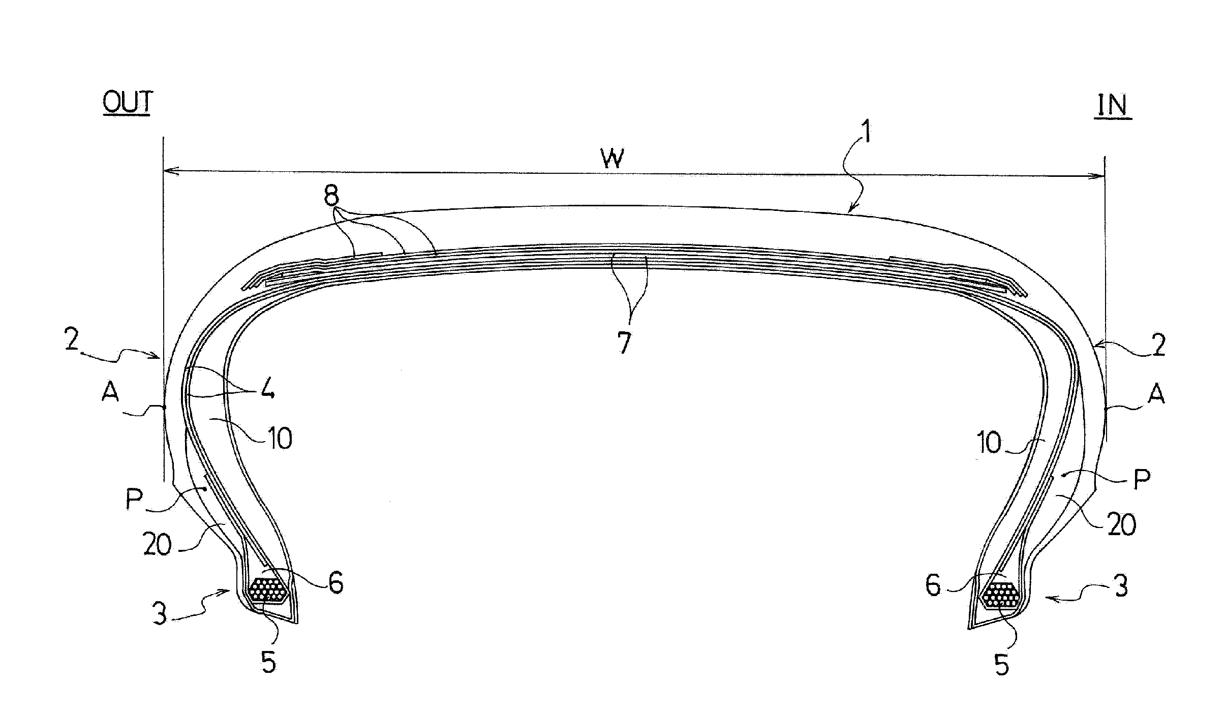
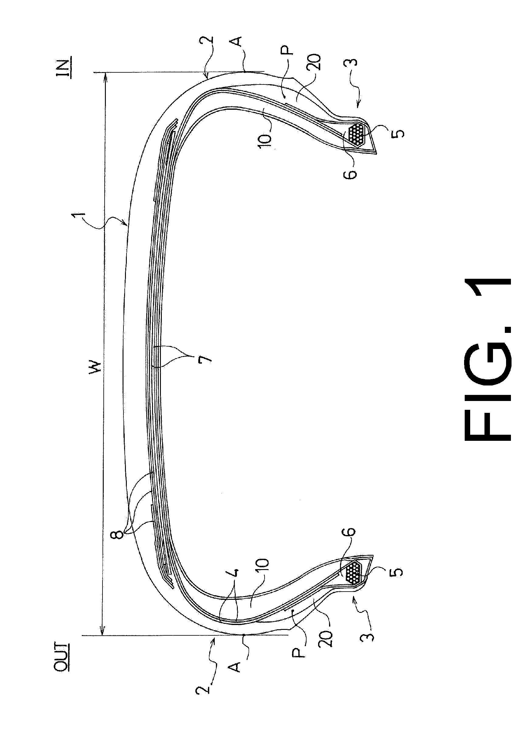
[0040]Ten types of test tires were fabricated for Conventional Examples 1 and 2, Comparative Examples 1 and 2, and Working Examples 1 to 6. These test tires were pneumatic run flat tires having a common tire size of 245 / 45R17. For each of the inner side reinforcing rubber layer and the outer side reinforcing rubber layer, the presence / absence of each of the reinforcing rubber layers, the volume ratios V1out / V1in, and V2in / V2out, the presence / absence of the cyclic polysulfide and compounded amount thereof, the tan δ at 60° C., the dynamic elastic modulus E′ at 60° C., and the reduction / non-reduction of volume were varied as shown in Table 1. Additionally, the material of the belt cover layer was varied as shown in Table 1. In all of the test tires, the center of gravity position P of the outer side reinforcing rubber layer was disposed inward in the tire radial direction of the tire maximum width position A. Composite fiber constituted by nylon fiber and aramid fiber was used for the...


PUM

PropertyMeasurementUnit
Temperatureaaaaaaaaaa
Percent by massaaaaaaaaaa

Abstract

A pneumatic run flat tire includes an inner side reinforcing rubber layer having a falcated cross-section and an outer side reinforcing rubber layer having a center of gravity position in a meridian cross-section that is positioned inward in a tire radial direction of a tire maximum width position disposed in a side wall portion. Volumes of the inner side reinforcing rubber layer and the outer side reinforcing rubber layer are each different on a vehicle inner side and a vehicle outer side when mounted on a vehicle.

Description

PRIORITY CLAIM[0001]Priority is claimed to Japan Patent Application Serial No. 2011-213254 filed on Sep. 28, 2011.BACKGROUND[0002]1. Technical Field[0003]The present technology relates to a pneumatic run flat tire and more particularly relates to a pneumatic run flat tire by which riding comfort when regular traveling can be maintained at a high level and run-flat durability can be enhanced.[0004]2. Related Art[0005]With pneumatic tires, a side-reinforced pneumatic run flat tire in which a reinforcing rubber layer having a falcated cross-section is inserted on an inner face of a side wall portion, and by which run-flat traveling is made possible based on the rigidity of this reinforcing rubber layer is known (e.g. see Japanese Unexamined Patent Application Publication No. 2010-023823A). With such a side-reinforced pneumatic run flat tire, there is a benefit in that run-flat traveling is achieved based on the tire structure without depending on a support body such as an inner ring or...

Claims


Application Information

Patent Timeline
IPC IPC(8): B60C17/00
CPCC08K5/372B60C17/0018B60C2017/0063B60C15/0018B60C2009/2038B60C2015/0621B60C15/0054B60C2001/0033C08L21/00B60C9/005B60C9/22B60C2015/0617Y10T152/10504
Inventor HORIUCHI, KENJI
Owner YOKOHAMA RUBBER CO LTD
Why Eureka
Try Eureka