Wireless charger system with radio controlled clock

a wireless charger and radio control technology, applied in the field of wireless chargers, can solve problems such as preventing integration of these applications with the wireless charger, and achieve the effects of preventing potential interference between the charging signal and the radio control clock signal, and minimizing the effect of hea

Inactive Publication Date: 2013-03-28
OREGON SCI GLOBAL DISTRIBUTION
View PDF0 Cites 1 Cited by
  • Summary
  • Abstract
  • Description
  • Claims
  • Application Information

AI Technical Summary

Benefits of technology

[0005]Accordingly, the present invention, in one aspect, is a wireless charger system comprising a wireless charger and a remote device wireless connected to the wireless charger. The wireless charger emits a charging signal at a first frequency range. The remote device receives a radio-controlled clock signal at a second frequency range, and modulates the radio-controlled clock signal via a carrier frequency to a modulated radio clock signal at a third frequency range. The modulated radio-controlled clock signal is not interfered with by the charging signal, allowing the remote device to send the modulated radio-controlled clock signal to the wireless charger for processing and display.
[0007]In another exemplary embodiment, the system further comprises a temperature sensor located at a distance from the wireless charger and connected to the wireless charger, allowing the wireless charger to display on its display panel a temperature output received from the temperature sensor while minimizing the effect of heat generated by the wireless charger to the temperature output of the temperature sensor. In a further embodiment, the distance is at least 10 cm.
[0008]In another aspect of the present invention, an alternate wireless charger system comprising a wireless charger, an adaptor of the wireless charger and a temperature sensor is disclosed. The wireless charger comprises a display panel. The adaptor is wiredly connected to the wireless charger. The temperature sensor is located intermediate to the wireless charger and the adaptor, and is located at a distance from the wireless charger. The temperature sensor is also wiredly connected to the wireless charger and the adaptor. The system minimizes the effect of the heat generated by the wireless charger to a temperature output of the temperature sensor. The temperature output of the temperature sensor is sent to the wireless charger and processing and displayed on the display panel.
[0009]There are many advantages to the present invention. One advantage is that potential interference between the charging signal and the radio-controlled clock signal is prevented. Generally, the frequency of the radio controlled clock signal varies a lot depending on the region, ranging from 40 kHz to several hundred kHz. The charging signal from the wireless charger contains a frequency in the above range, and interference may occur as a result, therefore affecting the performance of the radio controlled clock. By modulating the radio clock signal to another frequency range, interference is prevented, and this allows the wireless charger to incorporate the function of a radio clock signal.
[0010]Another advantage of the present invention is that by locating the temperature sensor at a distance from the wireless charger, the heat generated by the wireless charger will no longer skew the temperature sensed by the temperature sensor. As such, this improves the accuracy of the temperature sensor for measuring the temperature of the environment.

Problems solved by technology

However, a wireless charger emits signal at a frequency that may interfere with other applications such as a radio controlled clock, preventing integration of these applications with the wireless charger.

Method used


Image

  • Wireless charger system with radio controlled clock
  • Wireless charger system with radio controlled clock
  • Wireless charger system with radio controlled clock

Examples


Embodiment Construction

[0013]As used herein and in the claims, “comprising” means including the following elements but not excluding others.

[0014]As used herein and in the claims, “couple” or “connect” refers to electrical coupling or connection either directly or indirectly via one or more electrical means unless otherwise stated.

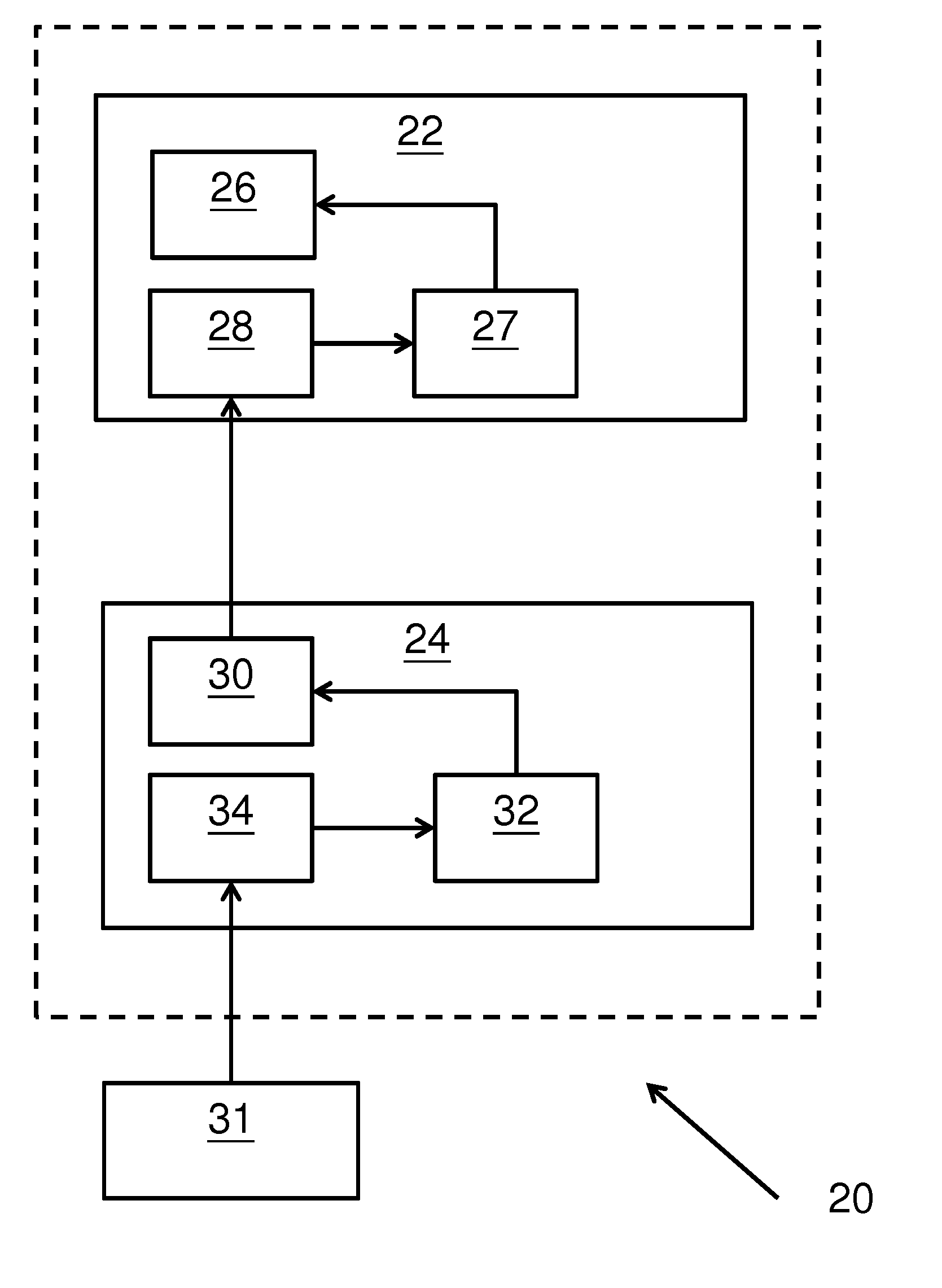
[0015]Referring now to FIG. 1, the first embodiment of the present invention is a wireless charger system 20 comprising a wireless charger 22 and a remote device 24. The wireless charger 22 comprises a display panel 26 for display various data and a demodulator 27. The wireless charger also comprises a wireless receiver 28. The remote device 24 comprises a wireless transmitter 30 corresponding to the wireless receiver 28, and also comprises a modulator 32 and a radio controlled clock (RCC) receiver 34.

[0016]In operation of the system, the RCC receiver 34 receives a RCC signal from a RCC station 31 at a second frequency range. The RCC signal generally ranges from 40 KHz to severa...


PUM


Abstract

A wireless charger system comprising a wireless charger and a remote device wireless connected to the wireless charger is disclosed. The wireless charger emits a charging signal at a first frequency range. The remote device receives a radio-controlled clock signal at a second frequency range, and modulates the radio-controlled clock signal via a carrier frequency to a modulated radio-controlled clock signal at a third frequency range. The modulated radio-controlled clock signal does not interfere with the charging signal, allowing the remote device to send the modulated radio-controlled clock signal to the wireless charger for display. An alternate wireless charger system comprising a wireless charger and an indoor temperature sensor is also disclosed.

Description

CROSS-REFERENCE TO RELATED APPLICATION[0001]This application claims benefit under 35 U.S.C. §119(e) of U.S. Provisional Application having Ser. No. 61 / 538,938 filed Sep. 26, 2011, which is hereby incorporated by reference herein in its entirety.FIELD OF INVENTION[0002]This invention relates to a wireless charger, and in particular a wireless charger for an electronic device with Radio-Controlled Clock function.BACKGROUND OF INVENTION[0003]Wireless chargers for mobile / electronic devices are more and more common as the hassle of finding the connector for the charger is eliminated. However, a wireless charger emits signal at a frequency that may interfere with other applications such as a radio controlled clock, preventing integration of these applications with the wireless charger.SUMMARY OF INVENTION[0004]In the light of the foregoing background, it is an object of the present invention to provide an alternate wireless charger system with a radio controlled clock.[0005]Accordingly, t...

Claims


Application Information

Patent Timeline
Patent Type & Authority Applications(United States)
IPC IPC(8): H02J7/00
CPCH04B5/0037H02J7/025G04R60/00H02J50/00H02J50/20
Inventor CHAN, RAYMOND
Owner OREGON SCI GLOBAL DISTRIBUTION
Why Eureka
Try Eureka