Controller provided with touch detection device

a technology of touch detection and control device, which is applied in the direction of pulse technique, instruments, coding, etc., can solve the problems of the inability to increase the variation in the area of contact corresponding to the intensity of pressure, and the inability to accurately detect the intensity of depressing operation. , to achieve the effect of increasing the dynamic range of touch detection signal, high accuracy and high accuracy

Inactive Publication Date: 2013-03-28
YAMAHA CORP
View PDF2 Cites 28 Cited by
  • Summary
  • Abstract
  • Description
  • Claims
  • Application Information

AI Technical Summary

Benefits of technology

[0014]In view of the foregoing prior art problems, it is an object of the present invention to provide an improved controller which is capable of touch detection corresponding to a depressed

Problems solved by technology

With such a construction, however, when the conductive patterns formed on the two flexible support members contact each other due to pressure (or load) acting on the surface of any of the support members, an amount of variation in the area of contact corresponding to the intensity of the pressure cannot be increased so much.
Thus, a dynamic range of the touch detection signal output in response to operation of the operator is so small that the intensity of the operation of the operator cannot be detected precisely with a high accuracy.
However, if the construction of the touch response sensor disclosed in patent literature 2 is applied to a push-button type operator, the detection value would become non-uniform due to an operated position and operated direction even in the case of depressing operation of same intensity, so that

Method used


Image

  • Controller provided with touch detection device
  • Controller provided with touch detection device
  • Controller provided with touch detection device

Examples


Embodiment Construction

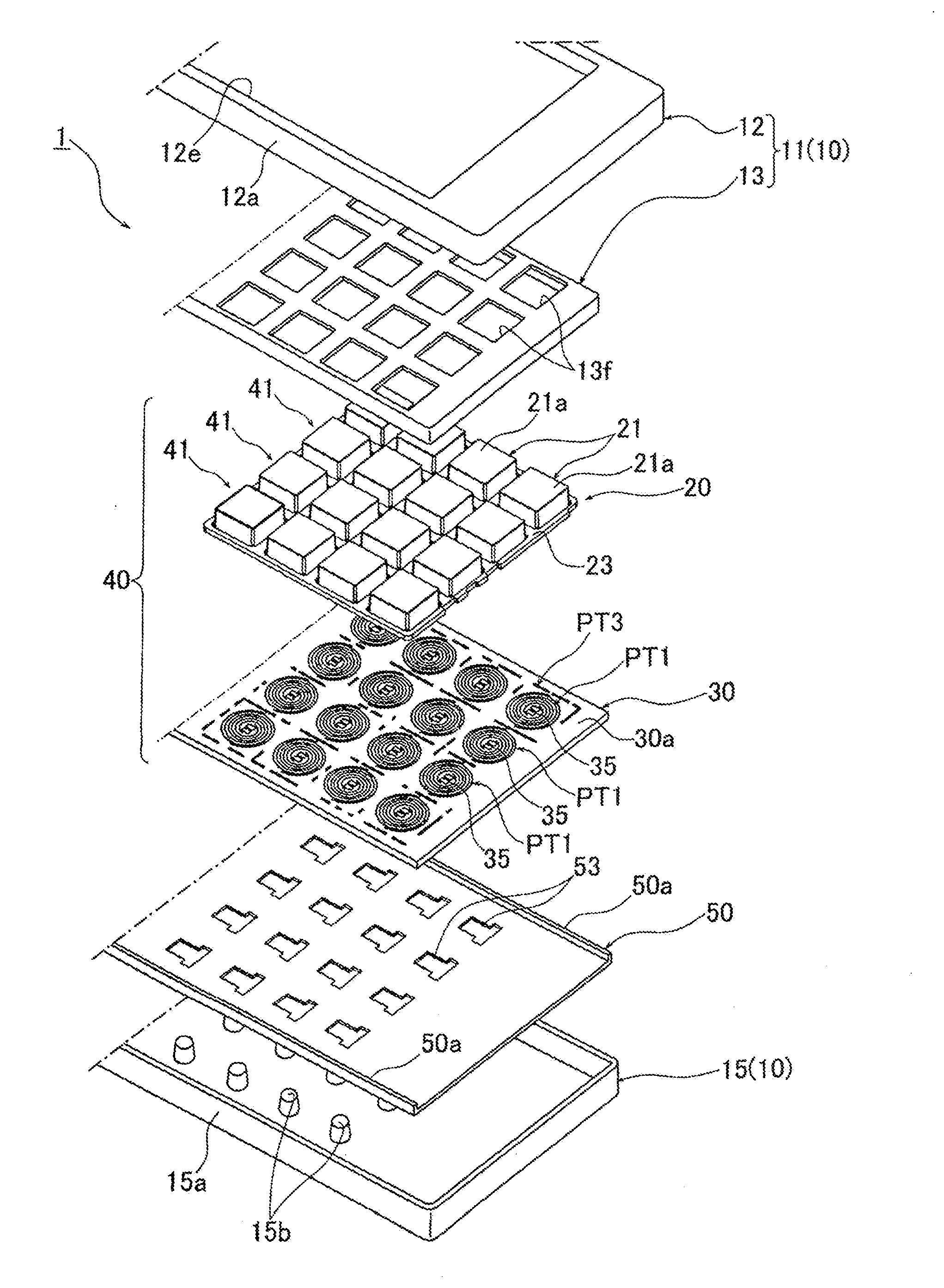
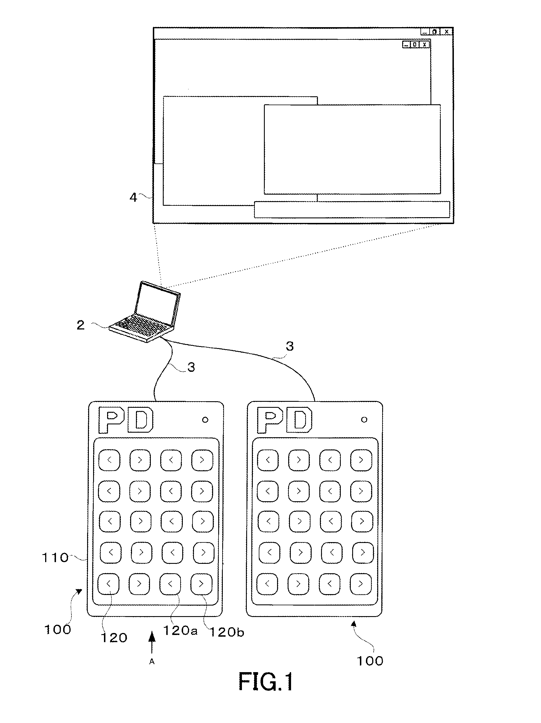
[0053]FIG. 1 is a diagram explanatory of a music production environment employing a controller 100 of the present invention provided with a first embodiment of a touch detection device 140, where the controller 100 is shown in a top plan view. As an example, the controller 100 is a remote controller for remote-controlling behavior related to a music production function performed by a computer, and the controller 100 will hereinafter be referred to also as “remote controller 100”. In FIG. 1, the remote controller 100 is communicatably connected with a personal computer (PC) 2 via a communication cable 3. An interface for interconnecting the controller 100 and the PC 2 may be a conventional interface, for example, of the USB (Universal Serial Bus) standard, and the interconnection may be of either a wired type or a wireless type.

[0054]The PC 2, which is a general-purpose personal computer having a general-purpose OS (Operating System) installed therein, has installed thereon, as one o...


PUM


Abstract

A controller includes an operating member operable by user's depression, and a touch detection device constructed to detect a depressing touch on the operating member. The touch detection device includes a movable contact pattern provided on the lower surface of the operating member, and a fixed contact pattern disposed underneath the operating member. One of the fixed and movable contact patterns is a coil-shaped contact pattern while the other of the fixed and movable contact patterns is a uniform surface pattern, at least one of the fixed and movable contact patterns has flexibility, and at least one of the fixed and movable contact patterns has a surface slanted from the center of the coil toward the outer peripheral edge of the coil. The coil-shaped contact pattern comprises first and second contact elements constituting a dual coil pattern.

Description

BACKGROUND[0001]The present invention relates to a controller provided with a touch detection device for performing touch detection responsive to depressing operation on a push-button type operating member (or operator), such as a remote controller suited for music production using a computer. The present invention also relates to a touch detection device constructed to perform touch detection in response to a movable contact pattern contacting a fixed contact pattern formed on a printed circuit board.[0002]Heretofore, it has been known to previously install, in a general-purpose computer, an application program for implementing a music production function (i.e., digital audio workstation program that will hereinafter be referred to as “DAW software”) and perform music production using the installed DAW software. In the music production using such DAW software, a user inputs or enters various commands and values of various parameters, by use of a display, mouse and keyboard provided...

Claims


Application Information

Patent Timeline
IPC IPC(8): H03K17/96G06F3/02
CPCH03K17/9647G06F3/02G10H1/0558G10H1/344G10H1/46G10H3/146G01L1/205G10H2220/275G10H2220/295G10H2220/561G10H2250/435G01L1/20G10H2220/066
Inventor TANAKA, HISANORIKOGA, RYOHEIENDO, JUNJISHIMIZU, TSUNEOOCHI, MITSUNORIAKABANE, TAKAHIRO
Owner YAMAHA CORP
Why Eureka
Try Eureka