
Scanner device and device for measuring three-dimensional shape of object

Active Publication Date: 2013-03-28
DAI NIPPON PRINTING CO LTD
View PDF10 Cites 70 Cited by
  • Summary
  • Abstract
  • Description
  • Claims
  • Application Information

AI Technical Summary

Benefits of technology

The present invention relates to a scanner apparatus that uses a line pattern of light to scan an object and capture surface information of the object. The apparatus includes an illumination unit that projects the line pattern onto the object, a pattern scanning mechanism that changes the position of the line pattern on the object with time, and an imaging unit that captures the image of the object onto a hologram recording medium. The hologram recording medium contains an image of a scatter body that is recorded by a reference light beam. The apparatus can be used in various applications such as surface inspection and object recognition.

Problems solved by technology

Conventionally, a line pattern is formed by condensing light by using an optical system such as a lens, or a line pattern is formed by transmitting light from a light source through a slit, however, the accuracy of the formed line pattern is not always sufficient.
For example, when a method for shaping by a slit is adopted, the structure is simple, but reflection and diffraction occur on the slit inner surfaces so that the contour of the line pattern easily becomes unclear.
Therefore, a high brightness discharge lamp such as a high pressure mercury lamp must be used as a light source, however, such a special light source has a comparatively short service life, and must be frequently replaced.
However, illumination using a coherent light source such as a laser poses a new problem of occurrence of speckles.
Therefore, when a line pattern is projected onto an object by using a laser light source, speckles occur on the line pattern on the object surface, and brightness unevenness occurs.
This is caused by the occurrence of speckle noise on the screen.
It is considered that the reason why speckles are caused when coherent light is used is that coherent lights reflected by portions of the diffusing and reflecting surface of a screen, etc., interfere with each other due to extremely high coherency.
However, if a line pattern used for measuring a three-dimensional shape includes brightness unevenness based on such speckles, a contour shape of the line pattern on an image cannot be accurately extracted, and correct shape analysis cannot be carried out.
However, to rotate or oscillate the scatter plate, a large-scale mechanical drive mechanism is required, so that the entire apparatus is increased in size and also increased in power consumption.

Method used


Image

  • Scanner device and device for measuring three-dimensional shape of object
  • Scanner device and device for measuring three-dimensional shape of object
  • Scanner device and device for measuring three-dimensional shape of object

Examples


Embodiment Construction

>>

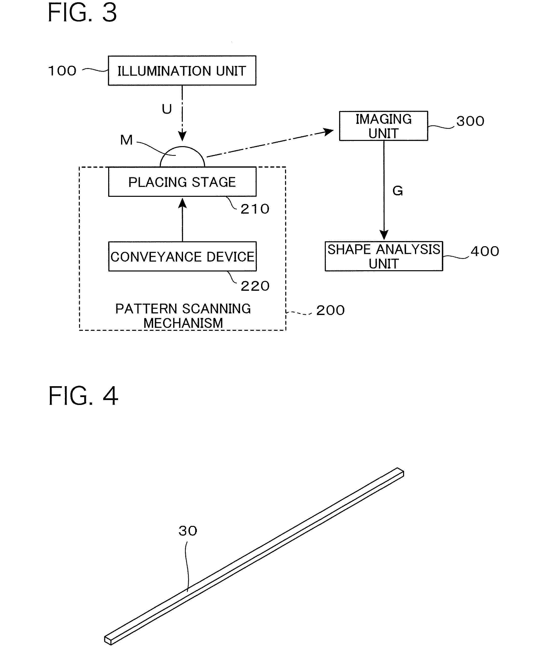
[0158]The present invention relates to a scanner apparatus using a coherent light source, and an apparatus for measuring a three-dimensional shape of an object by using the scanner apparatus. Therefore, here, a description is given of a basic configuration of the apparatus for measuring a three-dimensional shape according to the present invention.

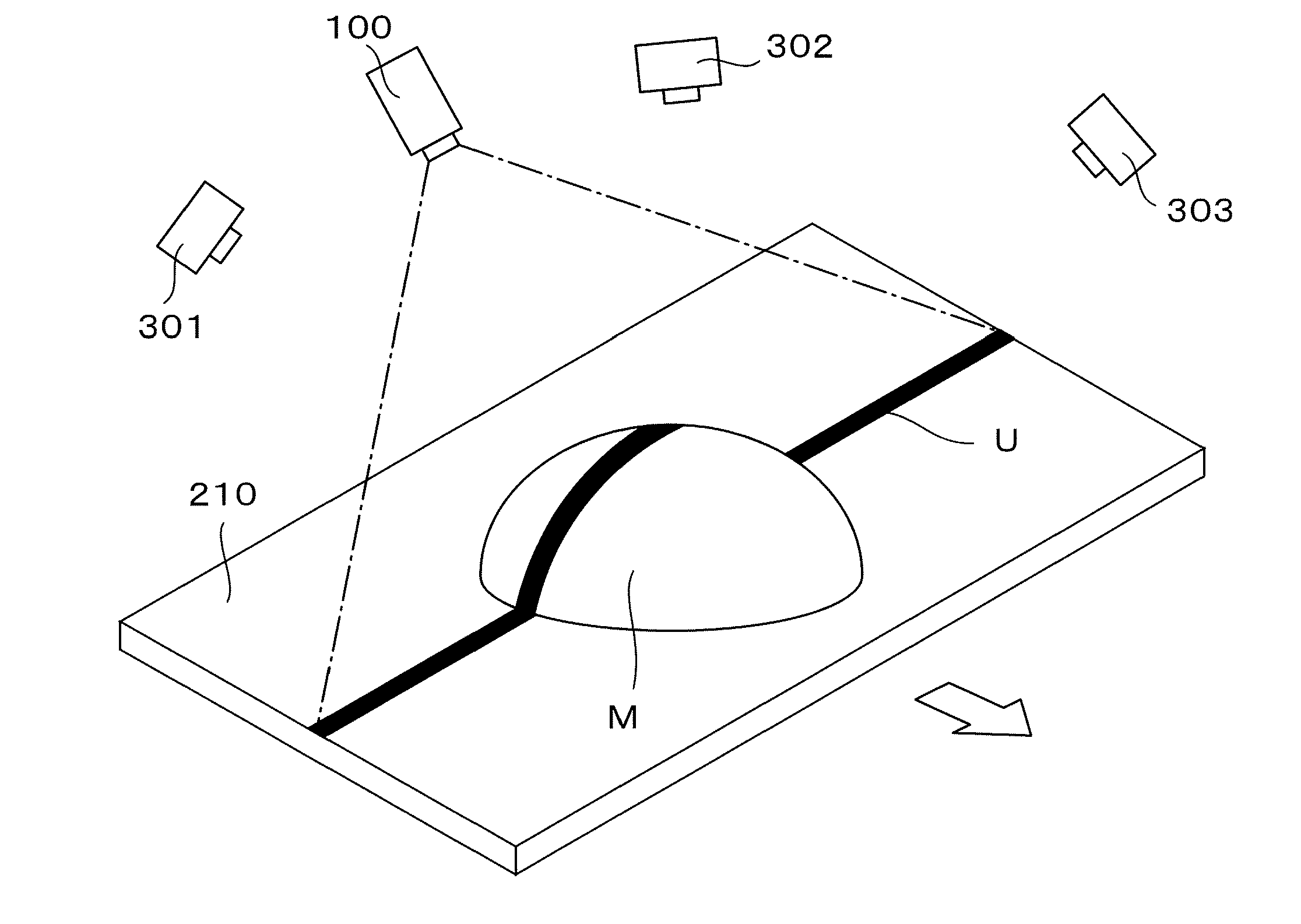
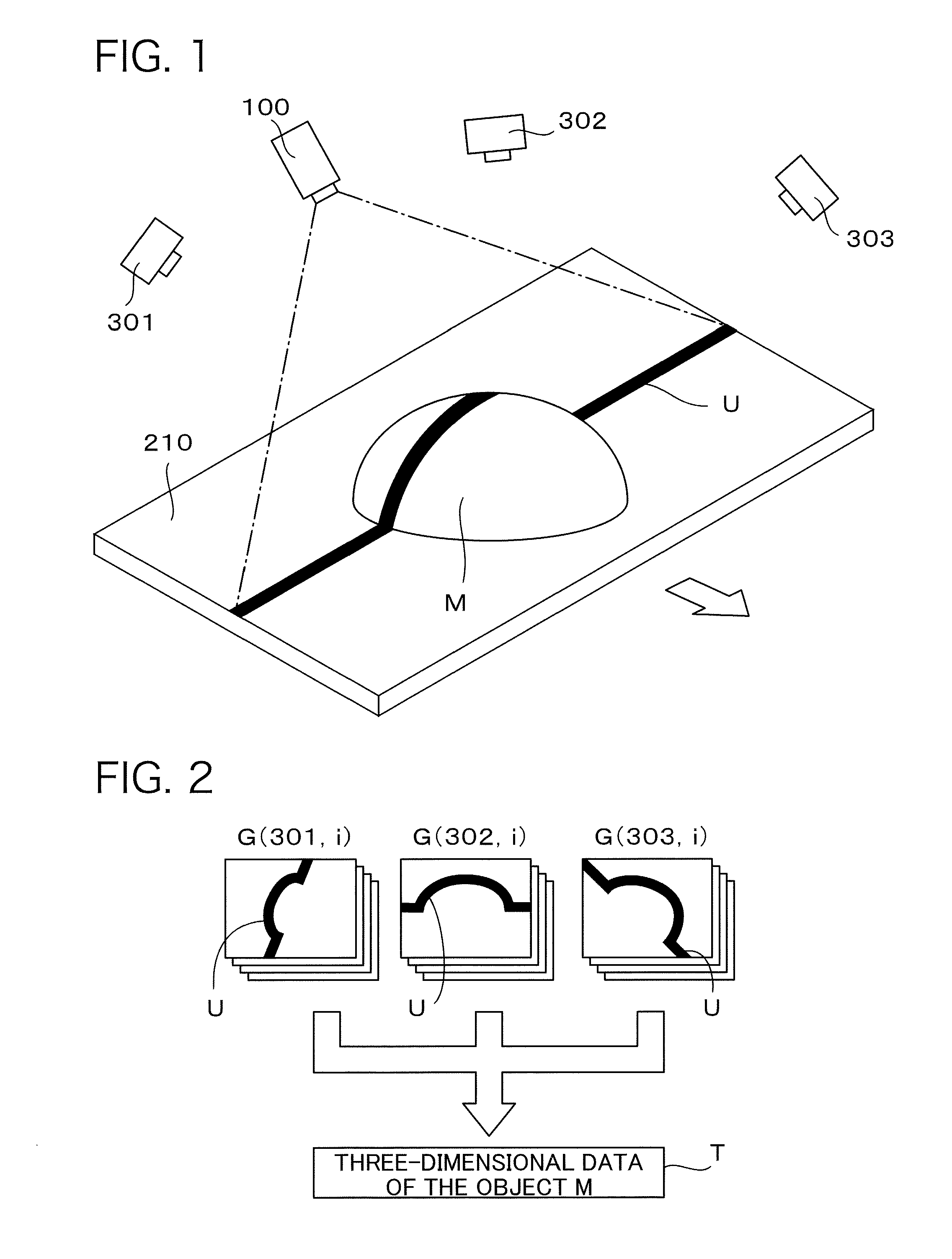
[0159]FIG. 1 is a perspective view showing a principle of measurement by the apparatus for measuring a three-dimensional shape of an object according to the present invention. Here, an example in which a three-dimensional shape of a semispherical object M is measured by using illumination from the illumination unit 100 is illustrated. As illustrated, the object M is placed on the upper surface of a placing stage 210, and when this placing stage 210 is moved in the direction illustrated by a white arrow in the drawing, the object M also moves in the same direction. On the other hand, above the object M, an illumination unit 100 is disposed...


PUM


Abstract

A laser beam is reflected by a light beam scanning device and irradiated onto a hologram recording medium. On the hologram recording medium, an image of a linear scatter body is recorded as a hologram by using reference light that converges on a scanning origin. The light beam scanning device bends the laser beam at the scanning origin and irradiates the laser beam onto the hologram recording medium. At this time, by changing a bending mode of the laser beam with time, an irradiation position of the bent laser beam on the hologram recording medium is changed with time. Diffracted light from the hologram recording medium produces a reproduction image of the linear scatter body on a light receiving surface of the stage. When an object is placed on the light receiving surface, a line pattern is projected by hologram reproduction light, so that the projected image is captured and a three-dimensional shape of the object is measured.

Description

TECHNICAL FIELD[0001]The present invention relates to a scanner apparatus that projects a line pattern of light onto an object to scan it. The present invention also relates to an apparatus for measuring a three-dimensional shape of an object by projecting a line pattern of light onto the object and obtaining a image of the projected pattern to create three-dimensional shape data by analyzing the obtained image.BACKGROUND ART[0002]An apparatus that measures a three-dimensional shape of an object is generally called a three-dimensional scanner, and apparatuses based on various principles are known. For example, Japanese Unexamined Patent Publication No. 2001-12942 discloses a three-dimensional scanner that carries out shape measurement by detecting a state of contact between an object to be measured and a contact probe by a sensor and measuring three-dimensional positions of the object surface. Further, Japanese Unexamined Patent Publication No. H07-91930 discloses a three-dimensiona...

Claims


Application Information

Patent Timeline
IPC IPC(8): G03H1/04G01B11/25
CPCG01B11/25G01B11/24G03H1/2286G03H1/32G03H2001/0033G03H2001/0439G03H2210/11G03H2222/36G03H2222/42G03H2222/54G03H2223/14G01B11/2518G03H1/0443G02B27/48G03H2001/0413G03H2001/0415G03H2001/2231G03H2001/2234G03H2001/2255G03H2001/2292G03H2210/20G03H2222/56G03H1/0005G03H1/30H04N7/18
Inventor KURASHIGE, MAKIOISHIDA, KAZUTOSHITAKANOKURA, TOMOEOYAGI, YASUYUKI
Owner DAI NIPPON PRINTING CO LTD
Learn More