Shunt protection module and method for series connected devices

a protection module and series connection technology, applied in the direction of emergency protection arrangements for limiting excess voltage/current, circuit arrangements, and arrangements responsive to excess voltage, can solve the problems of low power dissipation of shunt protection apparatuses disclosed in related prior art, and achieve low power dissipation

Active Publication Date: 2013-03-28
SILICON TOUCH TECH INC
View PDF8 Cites 4 Cited by
  • Summary
  • Abstract
  • Description
  • Claims
  • Application Information

AI Technical Summary

Benefits of technology

[0011]The main objective of the invention is to provide a shunt protection module and method that have low power dissipation.
[0012]The shunt protection module and method for series connected devices use multiple shunt semiconductors and a control unit. The shunt semiconductors correspond respectively to multiple target devices. Each shunt semiconductor connects to a corresponding target device in parallel. The control unit connects to trigger terminals of the shunt semiconductors. Because each shunt semiconductor has a characteristic that with the higher voltage the trigger terminal is input, the lower the electrical potential difference between shunt terminals is, and the control unit outputs a trigger voltage that is equal to the electrical potential difference on at least two adjacent target devices to the shunt semiconductor corresponding to a failed target device, an electrical potential difference on the shunt semiconductor is low when it operates. The shunt protection module and method ensure providing high trigger voltage to the shunt semiconductor corresponding to the failed target device so the power dissipation of the shunt protection module of the present invention can be reduced as low as possible and lower than the conventional shunt protection apparatuses thereof.

Problems solved by technology

However, designing a shunt protection apparatus that has low power dissipation is an important issue to be solved.
However, the power dissipation of the shunt protection apparatus disclosed in the related prior art cannot be lower than a quarter of the power dissipation of the corresponding LED.

Method used


Image

  • Shunt protection module and method for series connected devices
  • Shunt protection module and method for series connected devices
  • Shunt protection module and method for series connected devices

Examples


Embodiment Construction

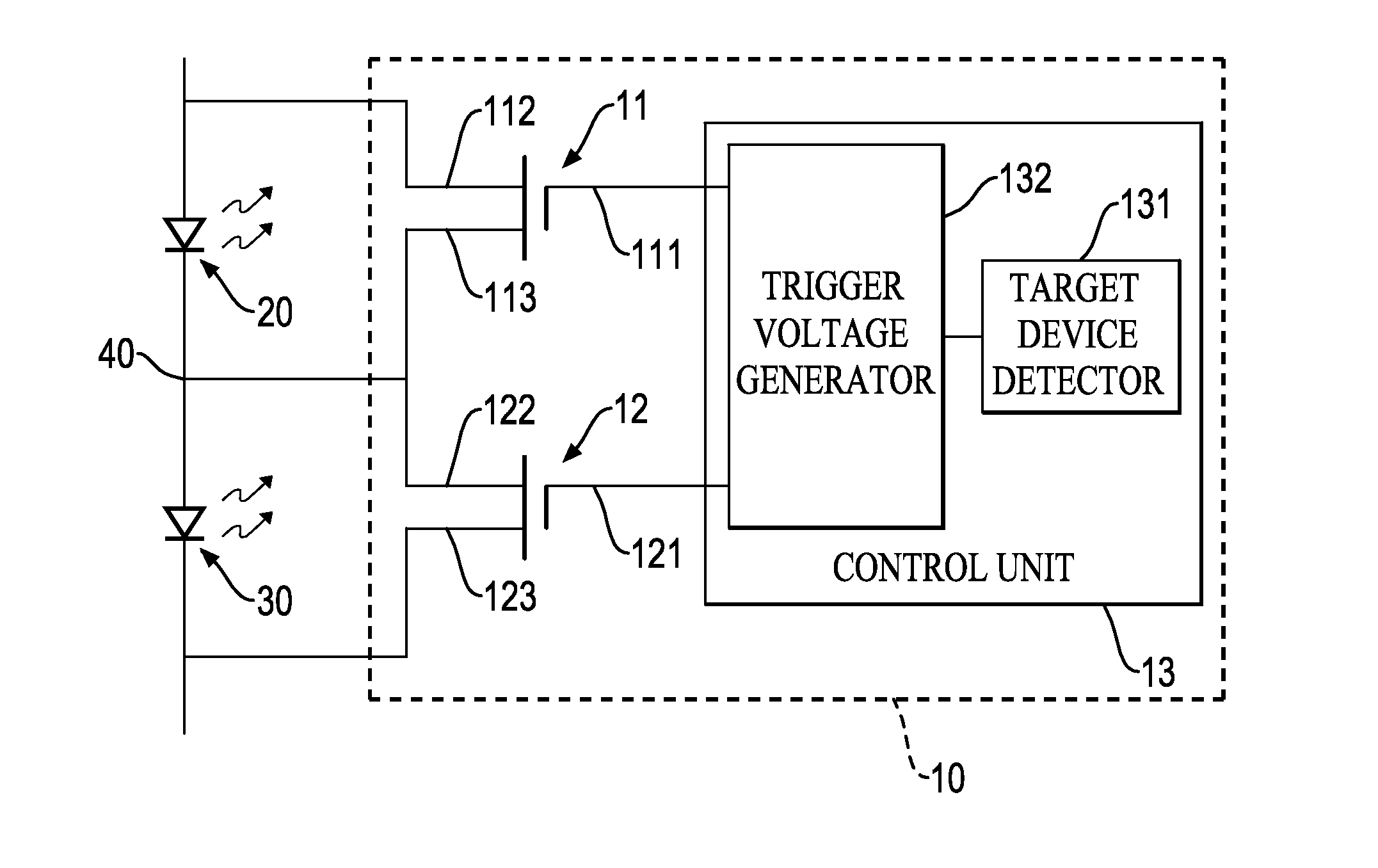
[0022]A shunt protection module in accordance with the present invention is used to connect to multiple target devices and comprises multiple shunt semiconductors and a control unit.

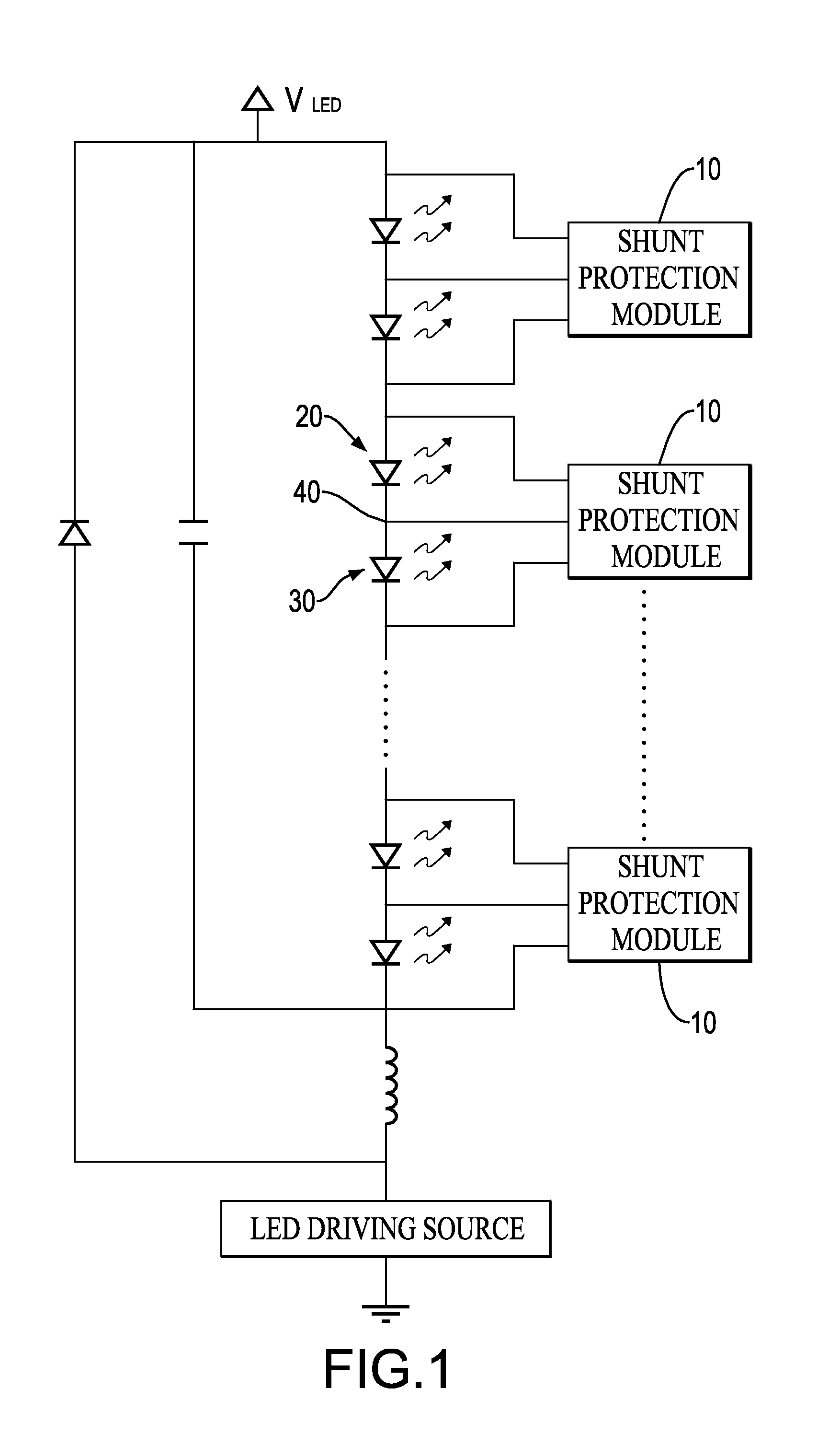
[0023]With reference to FIG. 1, an embodiment of the shunt protection module 10 of the present invention is applied to, but not limit to, an LED string, which includes multiple LEDs connected in series. Each shunt protection module connects to multiple adjacent target devices, such as connecting to two adjacent LEDs in the LED string in this embodiment. The two adjacent LEDs are exemplified as a first LED 20 and a second LED 30 hereinafter. An anode of the second LED 30 connects to a cathode of the first LED 20 in a node 40.

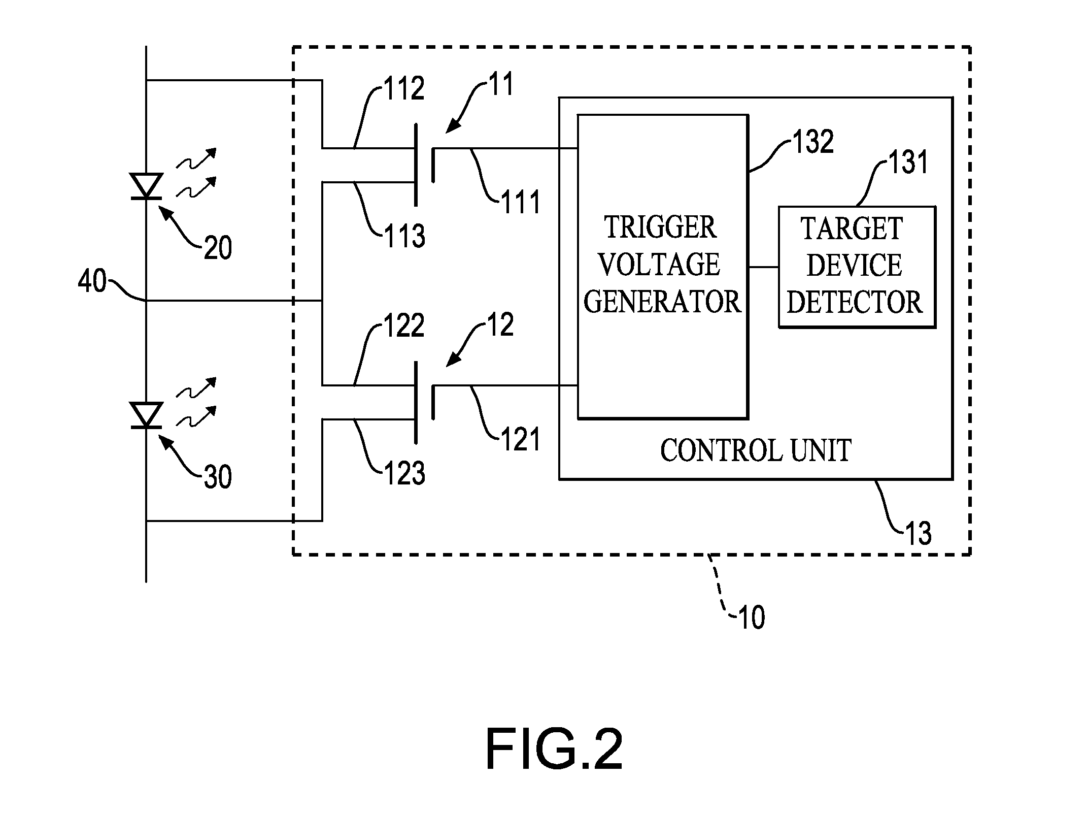
[0024]The amount of the shunt semiconductors corresponds to the amount of the target devices. With further reference to FIG. 2, two shunt semiconductors, which are a first shunt semiconductor 11 and a second shunt semiconductor 12, are implemented in this embodiment and correspond res...


PUM


Abstract

A shunt protection module and method for series connected devices use multiple shunt semiconductors and a control unit. The shunt semiconductors correspond respectively to multiple target devices. Each shunt semiconductor connects to a corresponding target device in parallel. The control unit connects to trigger terminals of the shunt semiconductors. Because each shunt semiconductor has a characteristic that with the higher voltage the trigger terminal is input, the lower the electrical potential difference between shunt terminals is, and the control unit outputs a trigger voltage that is equal to the electrical potential difference on at least two adjacent target devices to the shunt semiconductor corresponding to a failed target device, an electrical potential difference on the shunt semiconductor is low when it operates. The shunt protection module and method ensure providing high trigger voltage to the shunt semiconductor corresponding to the failed target device.

Description

BACKGROUND OF THE INVENTION[0001]1. Field of the Invention[0002]The present invention relates to a shunt protection module and method for series connected devices, and more particularly to a shunt protection module and method that have low power dissipation.[0003]2. Description of Related Art[0004]A conventional shunt protection apparatus is invented to ensure that series connected devices, such as multiple series connected LEDs, operate normally even if one of the series connected LEDs fails. However, designing a shunt protection apparatus that has low power dissipation is an important issue to be solved. U.S. Pat. No. 7,564,666 (related prior art hereinafter) disclosed a solution.[0005]With reference to FIG. 7, the related prior art disclosed a shunt protection circuit. Each shunt protection circuit corresponds to and is connected to a LED and has a first terminal 51, a second terminal 52, a metal oxide semiconductor (MOS) gated silicon controlled rectifier (SCR) 53, two diodes 54...

Claims


Application Information

Patent Timeline
Patent Type & Authority Applications(United States)
IPC IPC(8): H02H3/20H05B44/00
CPCH05B33/089H05B33/083Y02B20/341H05B45/48Y02B20/30H05B45/54H02H3/20
Inventor CHIN, CHI-YUANCHEN, KUEI-JYUN
Owner SILICON TOUCH TECH INC
Why Eureka
Try Eureka