Method and apparatus for adjusting a field of view for exposure of an x-ray system, and an x-ray system

Inactive Publication Date: 2013-03-28
GE MEDICAL SYST GLOBAL TECH CO LLC +1
View PDF17 Cites 32 Cited by
  • Summary
  • Abstract
  • Description
  • Claims
  • Application Information

AI Technical Summary

Benefits of technology

[0008]According to another embodiment of the invention, an X-ray system is provided. The X-ray system comprises: an X-ray source for emitting an X-ray to form a field of view for exposure on a patient; an image sensor arranged at a predetermined position in the X-ray system for capturing an image of the patient; a display for displaying the captured image of the patient for selection of a region of interest or a point of interest by a user on the image; a computing device configured to compute a target position of the X-ray source, wherein a

Problems solved by technology

However, existing digital X-ray systems only can preset a limited number of positions for automatic positioning, and the preset position should be selected by a radiographer before automatically positioning at the preset position.
The limited number of preset positions in the existing digital X-ray systems is far from satisfying clinical needs.
Generally, in some hospitals, it may need to image several hundreds of patients every day, and during the diagnosis, the field of view for exposure of the X-ray system should be manually adjusted almost for each patient, which,

Method used


Image

  • Method and apparatus for adjusting a field of view for exposure of an x-ray system, and an x-ray system
  • Method and apparatus for adjusting a field of view for exposure of an x-ray system, and an x-ray system
  • Method and apparatus for adjusting a field of view for exposure of an x-ray system, and an x-ray system

Examples


Embodiment Construction

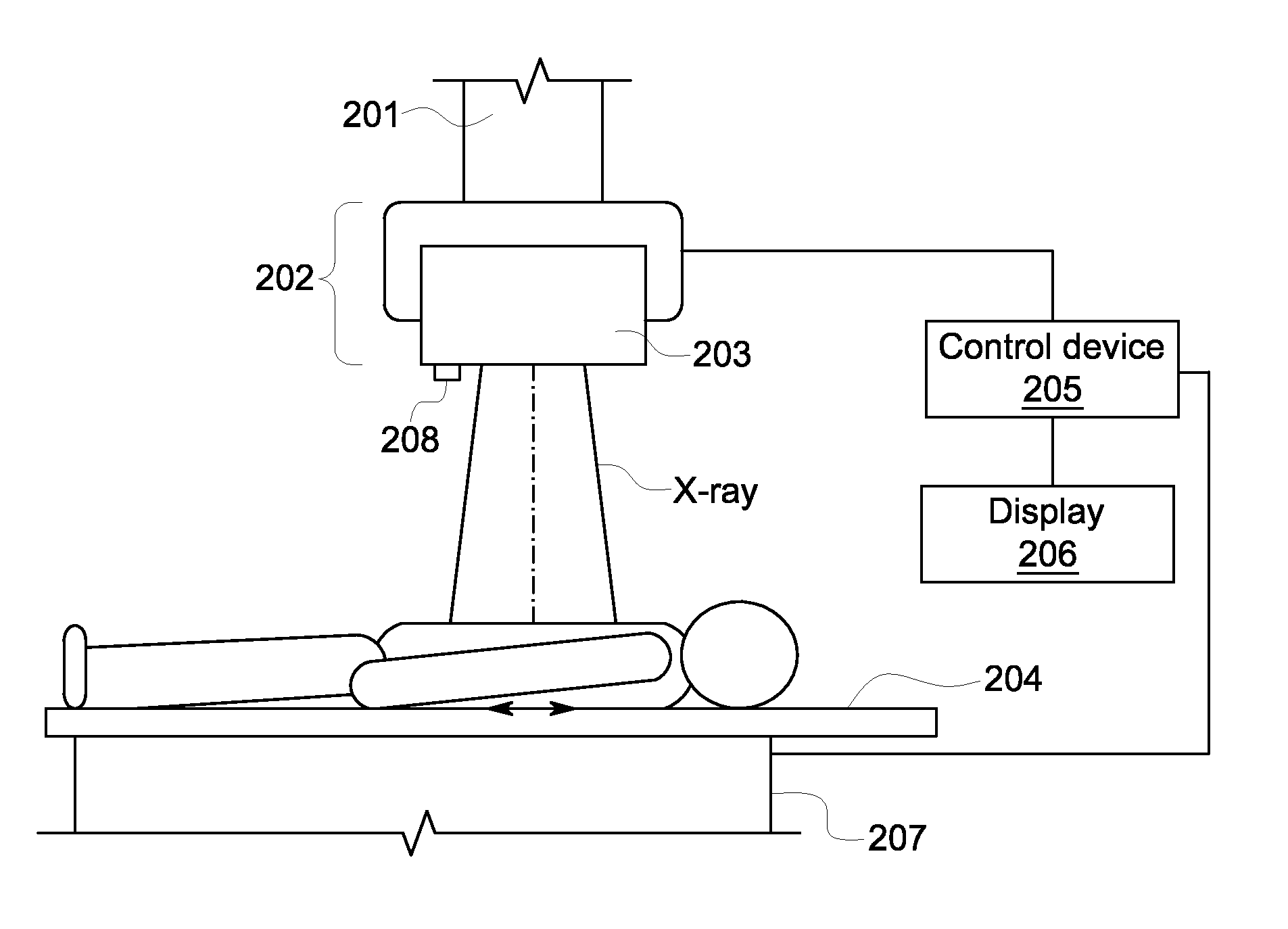
[0018]FIG. 2 is a schematic diagram of an X-ray system 200 according to an embodiment of the present invention. As shown in the figure, the X-ray system 200 includes an overhead tube suspensory system 201, an X-ray source 202, an examining table 204, a positioner 207 for moving the examining table, a control device 204 and a display 205. In addition, the X-ray system 200 includes an image sensor 208, which is fixed at a predetermined position in the X-ray system, for imaging the patient on the examining table 204. The image sensor 208 may be any of now known or later developed apparatus that can take an image, hereinafter an embodiment of the present invention will be explained by taking a digital camera as an example of the image sensor 208. The camera 208 is fixed at a position where it can capture an image of the patient on the examining table 204, and a distance of the position from other devices in the X-ray system 200 is measurable or known. In the embodiment shown in FIG. 2, ...


PUM


Abstract

A method for adjusting a field of view for exposure of an X-ray system is provided. The method comprises: capturing an image of a patient on an examining table of the system by an image sensor, wherein the image sensor is placed at a predetermined position in the system; displaying the captured image on a display for selection of a region of interest or a point of interest by a user on the image; automatically determining a target position of an X-ray source in response to the selection of the region of interest or the point of interest on the image, wherein a desired field of view for exposure covering the region of interest or the point of interest is obtained when the X-ray source is located at the target position; and automatically locating the X-ray source at the target position in response to the determination of the target position.

Description

BACKGROUND OF THE INVENTION[0001]Embodiments of the invention relate to X-ray systems, and in particular to a method and apparatus for adjusting a field of view for exposure of an x-ray system, and an X-ray system.[0002]FIG. 1 shows a prior art digital X-ray system 100 that includes an Overhead Tube Suspensory (OTS) system 101 for moving an X-ray source, an OTS console 102, a collimator 103 constituting the X-ray source (other components constituting the X-ray source are not shown due to the angle of view), a movable examining table 104, and a positioner 105 for moving the examining table 104. The collimator 103 is typically mounted below the tube that emits X-rays, which impinges upon the patient through a shutter of the collimator 103, wherein the size of the shutter of the collimator 103 defines the irradiation range of X-rays, i.e., the size of the region of the field of view for exposure (FOV) 106. The lateral positions of the tube and the collimator determine the position of t...

Claims


Application Information

Patent Timeline
IPC IPC(8): A61B6/00
CPCA61B6/52A61B6/06A61B6/548A61B6/4021A61B6/469A61B6/08
Inventor WANG, JIANYE, BINHUANG, YANNANHAN, YONGHUI
Owner GE MEDICAL SYST GLOBAL TECH CO LLC
Why Eureka
Try Eureka