
Beverage dispensing system with apparatus for controlling foaming and flow rate

a beverage dispenser and apparatus technology, applied in the direction of liquid dispensing, liquid flow controller, packaging, etc., can solve the problems of excessive foaming, excessive beverage foaming, excessive beverage foaming, etc., to reduce beverage foaming, improve operation, and improve productivity

Active Publication Date: 2013-04-04
ANHEUSER-BUSCH
View PDF13 Cites 6 Cited by
  • Summary
  • Abstract
  • Description
  • Claims
  • Application Information

AI Technical Summary

Benefits of technology

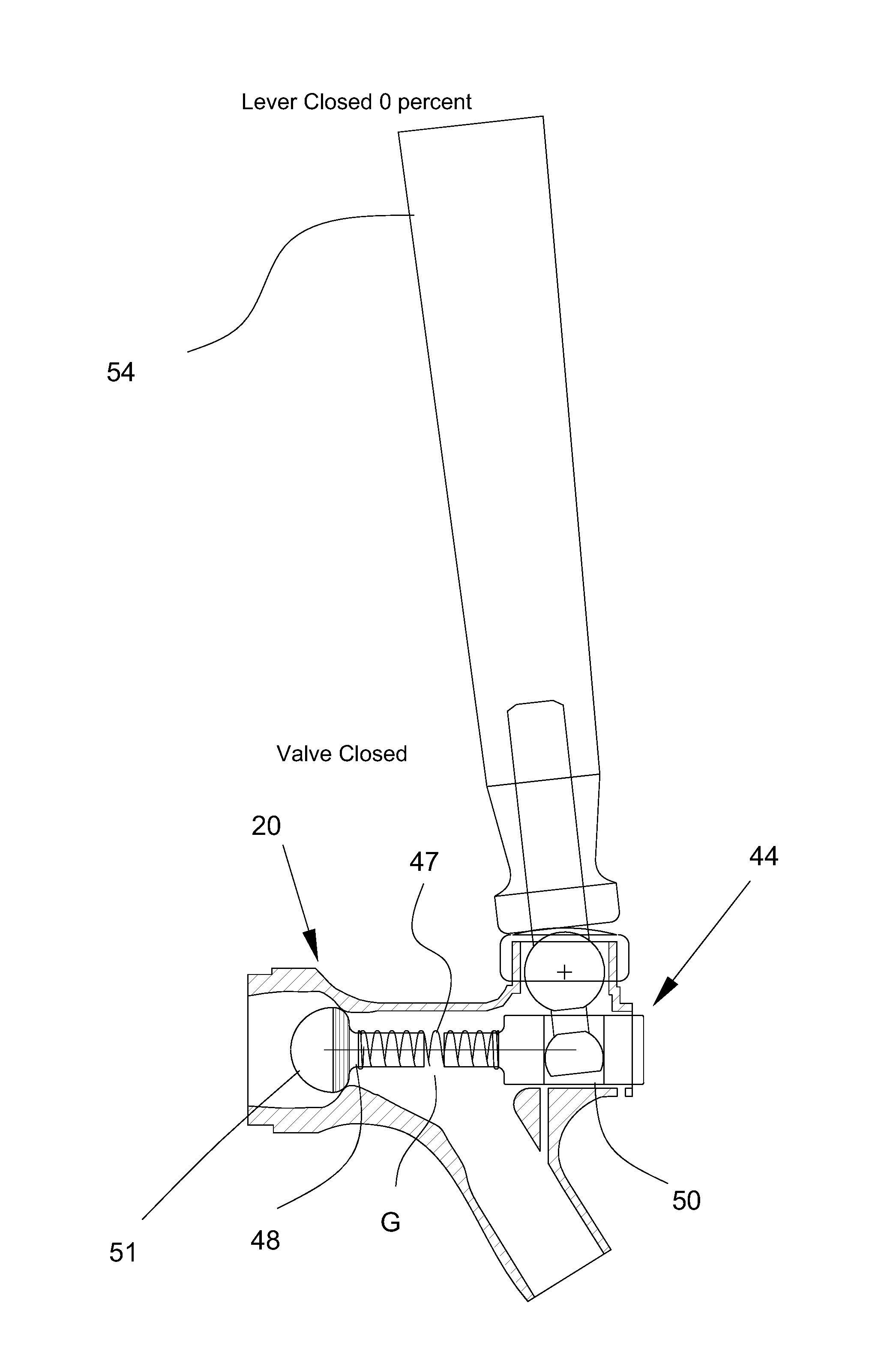
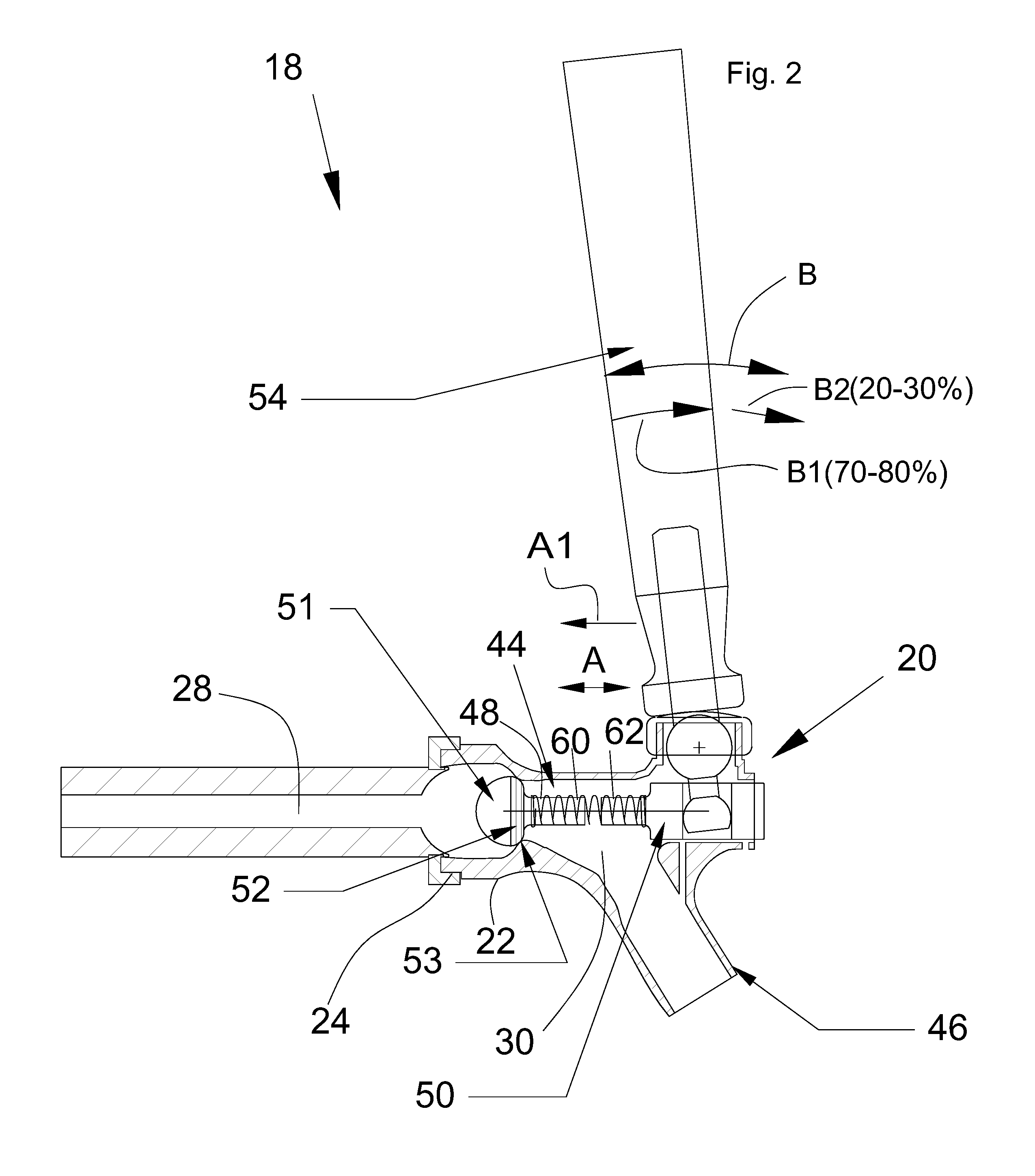
The present invention relates to a beverage dispensing system that overcomes shortcomings and provides a consistent, rapid opening of the faucet, resulting in improved satisfaction, even when operated by inexperienced or inattentive users. The invention resides in configuring a faucet such that the valve assembly will open sufficiently rapidly, irrespective of the speed of manual movement of the actuator, so as to decrease break up and foaming of the dispensed beverage. The biasing element can be incorporated into a standard faucet without outward changes to the appearance, so that the only noticeable difference between the faucet and an original faucet is the improved operation, that is, reduced beverage foaming regardless of the operator or manner of operation. The invention can also be incorporated into an existing faucet simply and inexpensively.

Problems solved by technology

Through observation and investigation, it has been found that one significant source of excessive foaming is opening the faucet too slowly.
Apparently, if a faucet is slowly opened, gas, in the form of carbon dioxide naturally occurring in and / or added to beverages such as draught beer, can be released through the valve at a larger than desirable rate, and results in break up of the liquid and excessive foaming condition in the dispensed beverage.
This shortcoming can be alleviated in many instances by rapidly manually opening the faucet, but non-professional operators don't typically know this, and, as a result, dispensing is more time consuming, much beer is lost, and customer satisfaction is reduced.

Method used


Image

  • Beverage dispensing system with apparatus for controlling foaming and flow rate
  • Beverage dispensing system with apparatus for controlling foaming and flow rate
  • Beverage dispensing system with apparatus for controlling foaming and flow rate

Examples


Embodiment Construction

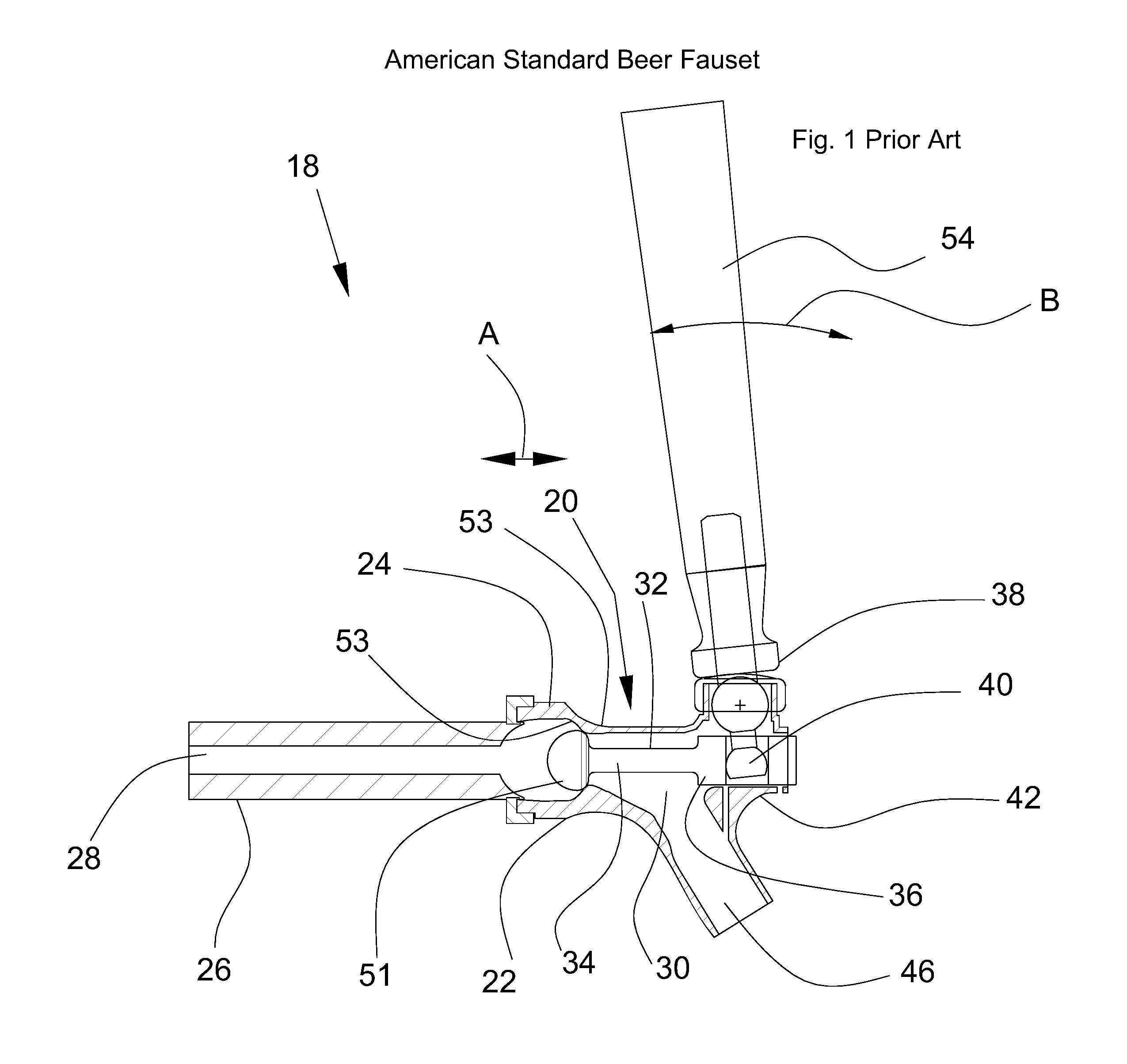
[0034]Referring now to the drawings, several embodiments of apparatus for controlling foaming and flow rate in a beverage dispensing system 18, e.g., for dispensing draught beer, are shown, like parts being identified by like numerals.

[0035]Referring to FIG. 1 first, a representative prior art standard American beer faucet 20 is illustrated, having a housing 22 including a threaded mounting end 24 adapted for threaded connection in a conventional manner to a container or line 26 which will contain beer 28. Housing 22 is oriented about horizontally, and defines a flow path 30 extending from mounting end 24 to an outlet or nozzle 46 through which the beer will be dispensed. Housing 22 includes an annular valve seat 53 extending about flow path 30 adjacent to mounting end 24. A barrel shape valve head 51 is disposed in flow path 30, between mounting end 24 and valve seat 52, and is configured and operable for forming a sealed condition with valve seat 52 when brought to bear thereagain...


PUM


Abstract

The beverage dispensing system includes a dispensing faucet defining a flow path, a valve head in the flow path movable between a closed position in sealed contact with a valve seat, and an open position. An actuator is manually movable to operate the faucet, and a biasing element is cooperable with the actuator and valve head such that an initial movement of the actuator will automatically cause sufficient energy to be stored or loaded in the biasing element for moving the valve head to the open position but without doing so. Occurrence of a subsequent predetermined event such as a further movement of the actuator will cause the stored energy to be automatically released to rapidly or nearly instantaneously move the valve head to the open position. As a result, no instruction or skill is required to operate the faucet to uniformly dispense pressurized beverages such as draught beer.

Description

[0001]This application is submitted under 35 U.S.C. 371 claiming priority to PCT patent application Serial No. PCT / US2011 / 041125, filed Jun. 20, 2011, which application claims the benefit of U.S. Provisional Application No. 61 / 356,412, filed Jun. 18, 2010.TECHNICAL FIELD[0002]This invention relates generally to a beverage dispensing system such as a beer faucet for dispensing draught beer, and, more particularly, to a beverage dispensing system including apparatus configured and operable for automatically reducing the foaming of the beverage as it is dispensed, while allowing a user to control flow rate of the beverage.BACKGROUND ART[0003]Beverage dispensing systems, particularly faucets for the pouring of draught beer or other naturally and / or artificially pressurized beverages, are well known. Typical pressurized beverages such as draught beer, contain a pressurizing medium, which is commonly a gas such as carbon dioxide. This pressurization medium can be naturally occurring, for ...

Claims


Application Information

Patent Timeline
IPC IPC(8): B67D1/00
CPCB67D1/1466B67D1/0081B67D1/1405B67D1/1422B67D2001/0089B67D2001/0094B67D1/0082B67D1/1411
Inventor TRULASKE, JAMES A.SCHMITT, STEPHEN M.
Owner ANHEUSER-BUSCH
Learn More