
System and method for improved control in wireless power supply systems

a wireless power supply and wireless technology, applied in the direction of batteries, exchanging data chargers, inductances, etc., can solve the problems of control system recognition and communication impairment in certain operating frequency ranges, and achieve the effect of reducing the risk of communication problems, avoiding operating characteristics, and simple and effective control

Inactive Publication Date: 2013-04-04
ACCESS BUSINESS GRP INT LLC
View PDF7 Cites 95 Cited by
  • Summary
  • Abstract
  • Description
  • Claims
  • Application Information

AI Technical Summary

Benefits of technology

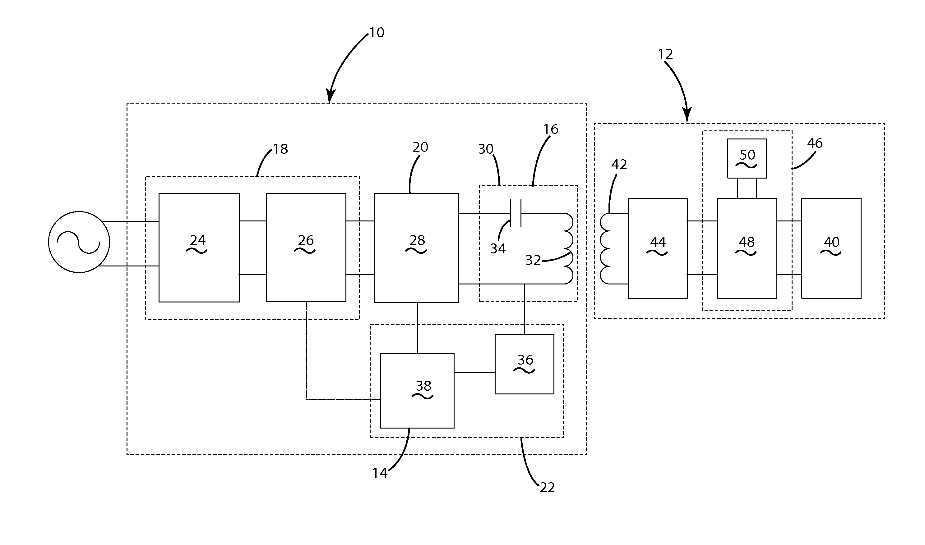
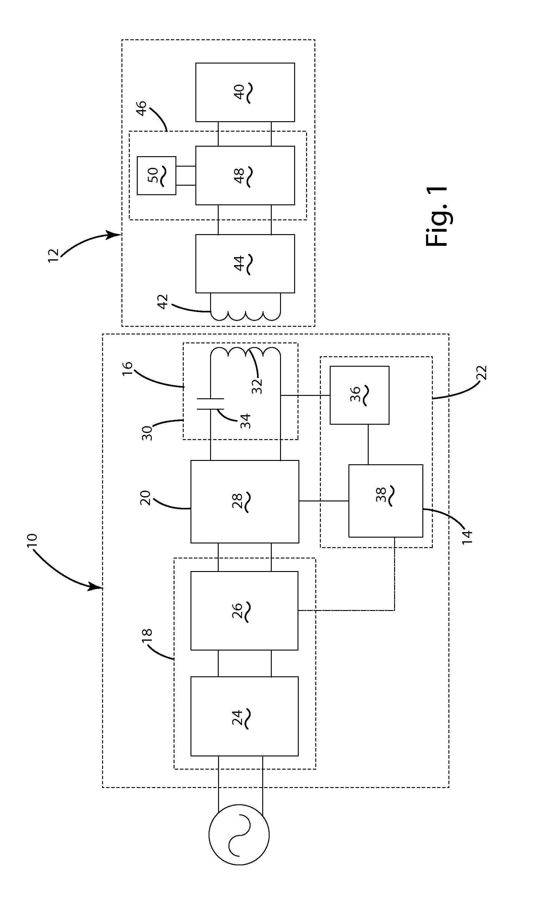
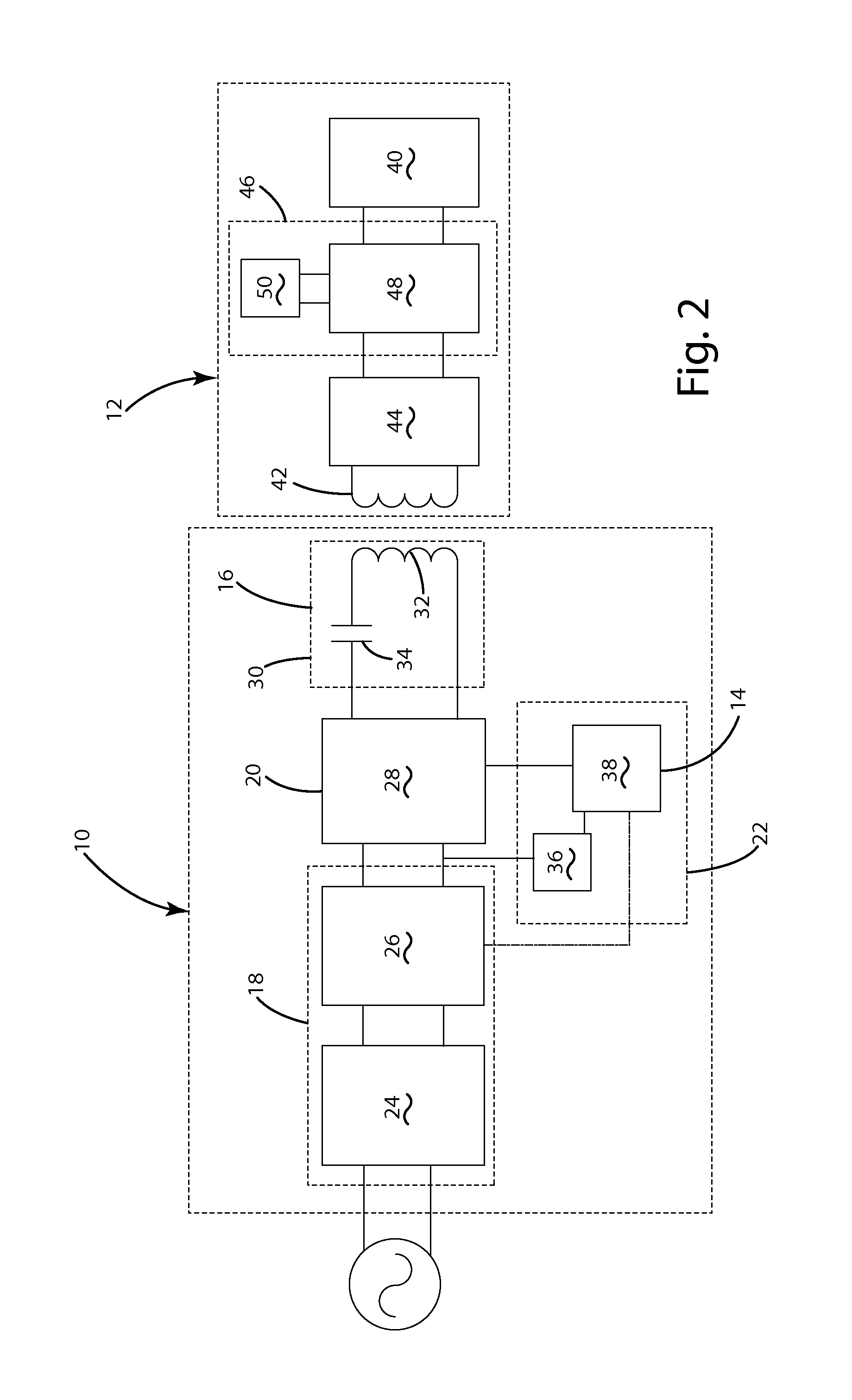
The present invention is a wireless power supply control system that can adjust its characteristics to supply the power needs of a remote device while avoiding operating characteristics that might adversely affect its operation. This system can detect operating characteristics that present adverse affects, maintain a record of those operating characteristics and avoid them once detected. The control system can use operating frequency adjustment as its primary control and avoid certain frequency ranges that may cause communication impairments. It can also use a secondary control mechanism when the primary control would otherwise want to go into a problematic frequency range. The control system can reduce the risk of problems with communications caused by operation in specific frequency ranges, interfere with proper operation of the remote device, and improve overall efficiency and reliability of wireless power supplies.

Problems solved by technology

For example, with a control system that use operating frequency adjustment as its primary control, the control system may recognize that communications are impaired in certain operating frequency ranges.

Method used


Image

  • System and method for improved control in wireless power supply systems
  • System and method for improved control in wireless power supply systems
  • System and method for improved control in wireless power supply systems

Examples


Embodiment Construction

[0024]A. Overview.

[0025]The present invention relates to wireless power supplies with adaptive control and methods for providing adaptive control of a wireless power supply. The systems and methods of the present invention generally relate to control of the wireless power supply in a way that addresses or avoids the potential issues, such as loss of communications, impairment of function or other problems, caused by operating a wireless power supply within certain adverse operating ranges. The present invention is well-suited for addressing the potential loss of communications that may occur when the wireless power supply is operating within parameters that create interference with, mask or otherwise hinder communications from the remote device. For example, the present invention may help address the loss of communications in a wireless power supply that receives communications from the remote device through backscatter modulation in which communications are reflected back to the wi...


PUM


Abstract

A wireless power supply with an adaptive control system that is capable of adjusting various operating characteristics and that avoids operating at those operating characteristics that present adverse affects, such as impaired communications or interference with operation of the remote device. In one embodiment, the control system is capable of adjusting two or more of the operating frequency, duty cycle, rail voltage and switching circuit phase. In one embodiment, the wireless power supply control system is configured to detect operating characteristics that present adverse affects, maintain a record of those operating characteristics and avoid those operating characteristics once detected. In another embodiment, the remote device may be configured to advise the wireless power supply control system of certain “keep-out” ranges that adversely affect operation of the remote device.

Description

BACKGROUND OF THE INVENTION[0001]The present invention relates to wireless power supply systems, and more particularly to systems and methods for improving control in a wireless power supply system.[0002]Many conventional wireless power supply systems rely on inductive power transfer to convey electrical power without wires. A typical inductive power transfer system includes an inductive power supply that uses a primary coil to wirelessly transfer energy in the form of a varying electromagnetic field and a remote device that uses a secondary coil to convert the energy in the electromagnetic field into electrical power. Recognizing the potential benefits, some developers have focused on producing wireless power supply systems with adaptive control systems. Adaptive control systems may give the wireless power supply the ability to adapt operating parameters over time to maximize efficiency and / or control the amount of power being transferred to the remote device.[0003]Conventional ada...

Claims


Application Information

Patent Timeline
IPC IPC(8): H02J17/00H01F38/14
CPCH02J7/025H02J17/00H01F38/14H02J50/12H02J2207/20H02J50/80H02J7/00034H02J50/60H02J7/00
Inventor TAYLOR, JOSHUA B.MOORE, COLIN J.BAARMAN, DAVID W.MOLLEMA, SCOTT A.MOES, BENJAMIN C.KUYVENHOVEN, NEIL W.NIBBELINK, MATTHEW J.
Owner ACCESS BUSINESS GRP INT LLC
Learn More