Signal processor, filter, control circuit for power converter circuit, interconnection inverter system and pwm converter system

a control circuit and power converter technology, applied in the direction of motor/generator/converter stopper, dynamo-electric converter control, instruments, etc., can solve the problems of inability to design the control system by using a linear control theory, inability to analyze the system, and inability to achieve linearity and time-invariance. , to achieve the effect of maintaining linearity and time-invarian

Inactive Publication Date: 2013-04-04
DAIHEN CORP
View PDF20 Cites 55 Cited by
  • Summary
  • Abstract
  • Description
  • Claims
  • Application Information

AI Technical Summary

Problems solved by technology

A problem, however, is that designing the control system of the control circuit 7 requires tremendous work.
However, since the fixed-to-rotating coordinate converter 78 and the rotating-to-fixed coordinate converter 79 perform nonlinear time-varying processes, it was not possible to design the control system by using a linear control theory.
Further, system analysis was not possible, either, since the control system includes nonlinear time-varying processing.

Method used


Image

  • Signal processor, filter, control circuit for power converter circuit, interconnection inverter system and pwm converter system
  • Signal processor, filter, control circuit for power converter circuit, interconnection inverter system and pwm converter system
  • Signal processor, filter, control circuit for power converter circuit, interconnection inverter system and pwm converter system

Examples


first embodiment

[0104]Hereinafter, description will be made for a case where a signal processor which performs the process given by the transfer function matrix GI expressed by Equation (12) above is used as an electric current controller in a control circuit of an interconnection inverter system, as the present invention.

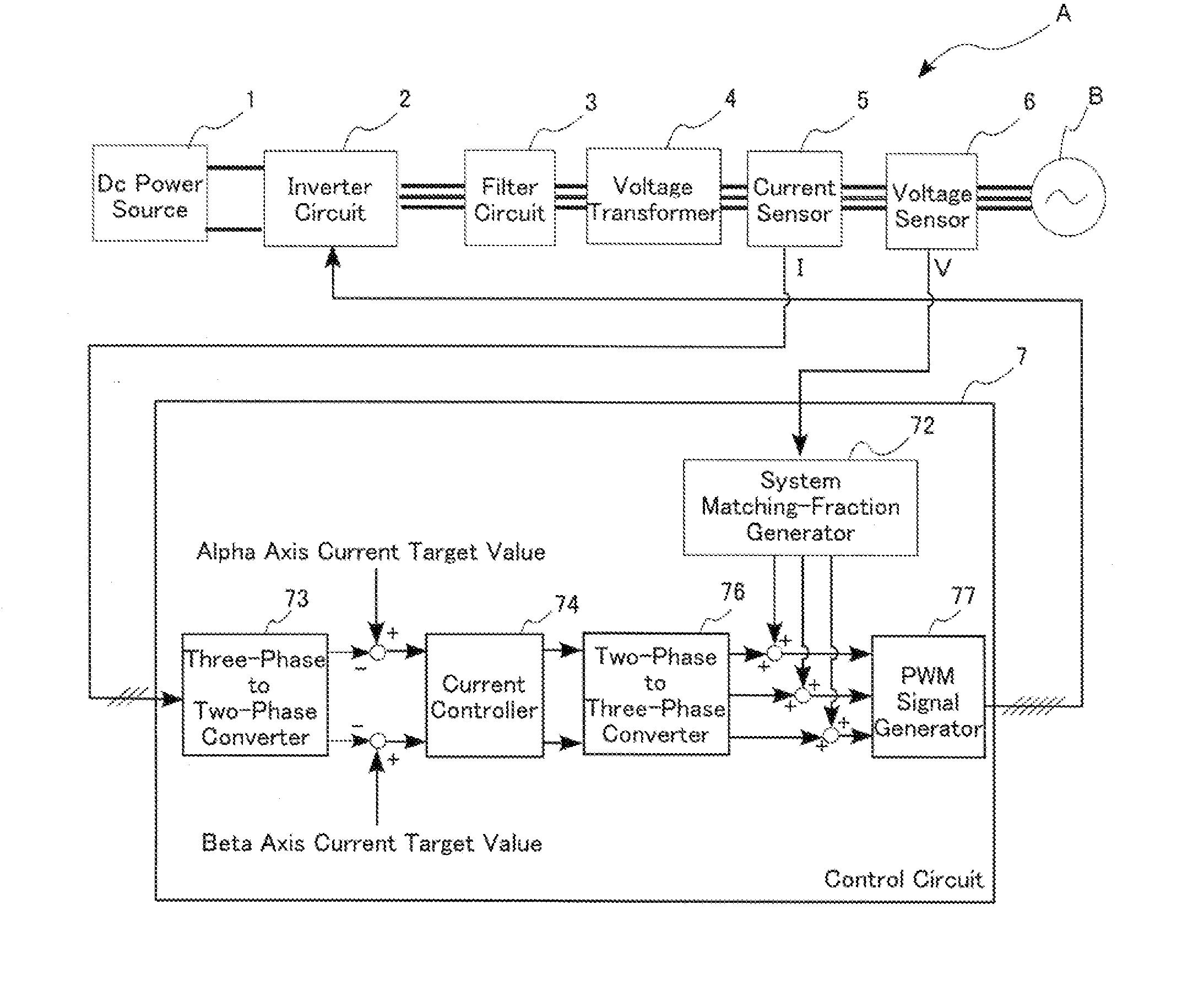
[0105]FIG. 6 is a block diagram for describing an interconnection inverter system according to the first embodiment.

[0106]As shown in the figure, an interconnection inverter system A includes a DC power source 1, an inverter circuit 2, a filter circuit 3, a voltage transformer circuit 4, a current sensor 5, a voltage sensor 6, and a control circuit 7.

[0107]The DC power source 1 is connected to the inverter circuit 2. The inverter circuit 2, the filter circuit 3, and the voltage transformer circuit 4 are connected in series in this order, to respective output lines of the phase U, phase V and phase W outputs, and then to a three-phase AC electrical power system B. The current senso...

second embodiment

[0138]The process represented by the transfer function of the element (1, 1) and the element (2, 2) in the matrix GI allows the positive-phase and the negative-phase sequence components in the fundamental wave component to pass through without changing their phases (see FIG. 7(a)). Therefore, it is possible to perform control on both of the positive-phase and the negative-phase sequence components in the fundamental wave component if the element (1, 2) and the element (2, 1) are “0” in the matrix GI represented by the Equation (12). In this case, there is no component enhancement unlike in the case where only the positive phase sequence component is controlled (where the matrix GI represented by Equation (12) is utilized), so the integral gain KI must be given a larger value accordingly. Hereinafter, description will be made for a second embodiment, where both of positive-phase and negative phase sequence components in the fundamental wave component are controlled.

[0139]FIG. 9 is a ...

third embodiment

[0148]FIG. 11 is a block diagram for describing a control circuit according to the In this figure, elements which are identical with or similar to those in the control circuit 7 in FIG. 6 are indicated by the same reference codes.

[0149]FIG. 11 shows a control circuit 7″, which differs from the control circuit 7 (see FIG. 6) according to the first embodiment in that it does not have the three-phase to two-phase converter 73 and the two-phase to three-phase converter 76, and that the current controller 74″ provides direct control using the current signals Iu, Iv, Iw.

[0150]Since three-phase to two-phase conversion and two-phase to three-phase conversion are expressed by Equation (1) and Equation (4), a process in which the three-phase to two-phase conversion is followed by the process represented by the matrix G of the transfer function and then followed by two-phase to three-phase conversion is represented by a transfer function matrix G′ shown as Equation (14) below:

G′=23[10-1232-12...


PUM


Abstract

A signal processor is configured to perform a process equivalent to performing a series of fixed-to-rotating coordinate conversion, a predetermined process and then rotating-to-fixed coordinate conversion, while maintaining linearity and time-invariance. The signal processor performs a process given by the following matrix G:G=[F(s+jω0)+F(s-jω0)2F(s+jω0)-F(s-jω0)2j-F(s+jω0)-F(s-jω0)2jF(s+jω0)+F(s-jω0)2]where F(s) is a transfer function representing the predetermined process, ω0 is a predetermined angular frequency and j is the imaginary unit.

Description

BACKGROUND OF THE INVENTION[0001]1. Field of the Invention[0002]The present invention relates to signal processors, filters, and control circuits for controlling output or input of power converter circuits. The present invention also relates to interconnection inverter systems and PWM converter systems using the control circuits.[0003]2. Description of the Related Art[0004]Interconnection inverter systems convert DC (direct current) power which is generated by solar cells for example, to AC (alternate current) power for supply to electrical power systems. (See JP-A-2009-44897, for example.)[0005]FIG. 36 is a block diagram for describing a conventional interconnection inverter system.[0006]The interconnection inverter system A100 converts power generated by a DC power source 1 for supply to a three-phase electrical power system B. Hereinafter, the three phases will be called phase U, phase V and phase W.[0007]An inverter circuit 2 receives a DC voltage from the DC power source 1, and...

Claims


Application Information

Patent Timeline
Patent Type & Authority Applications(United States)
IPC IPC(8): H02P4/00G06F17/14H03H17/06H02M1/12
CPCH02P4/00H02M1/12H02P21/00H03H17/06G06F17/147G01R25/00H02M7/48H02M1/0003H02P21/22H02M7/44
Inventor OHORI, AKIHIROHATTORI, NOBUYUKI
Owner DAIHEN CORP
Why Eureka
Try Eureka