Digital Switching Converter Control

a digital control and converter technology, applied in the direction of electric variable regulation, process and machine control, instruments, etc., can solve the problem that the forward voltage of individual leds may be significantly differen

Active Publication Date: 2013-04-04
INFINEON TECH AG
View PDF12 Cites 24 Cited by
  • Summary
  • Abstract
  • Description
  • Claims
  • Application Information

AI Technical Summary

Benefits of technology

[0007]A control circuit is configured to control the operation of a switching converter to provide a regulated load current to a load. The switching converter includes an inductor and a high-side and a low side-transistor for switching the load current provided via the inductor. The circuit includes a digital modulator configured to provide a modulated signal having a duty cycle determined by a digital duty cycle value. A current sense circuit is coupled to at least one of the transistors and is configured to regularly sample a load current value. A comparator is coupled to the current sense circuit and is configured to compare the sampled load current value with a first threshold and provide a respective comparator output signal The first threshold is dependent on a defined desired output current and the comparator output signal is indicative of whether the sampled current value is lower or greater than the desired output current. A regulator is configured to receive the comparator output signal and to calculate an updated digital duty cycle value.

Problems solved by technology

Further, the forward voltages of the individual LEDs may significantly differ due to unavoidable tolerances caused by the production process.

Method used


Image

  • Digital Switching Converter Control
  • Digital Switching Converter Control
  • Digital Switching Converter Control

Examples


Embodiment Construction

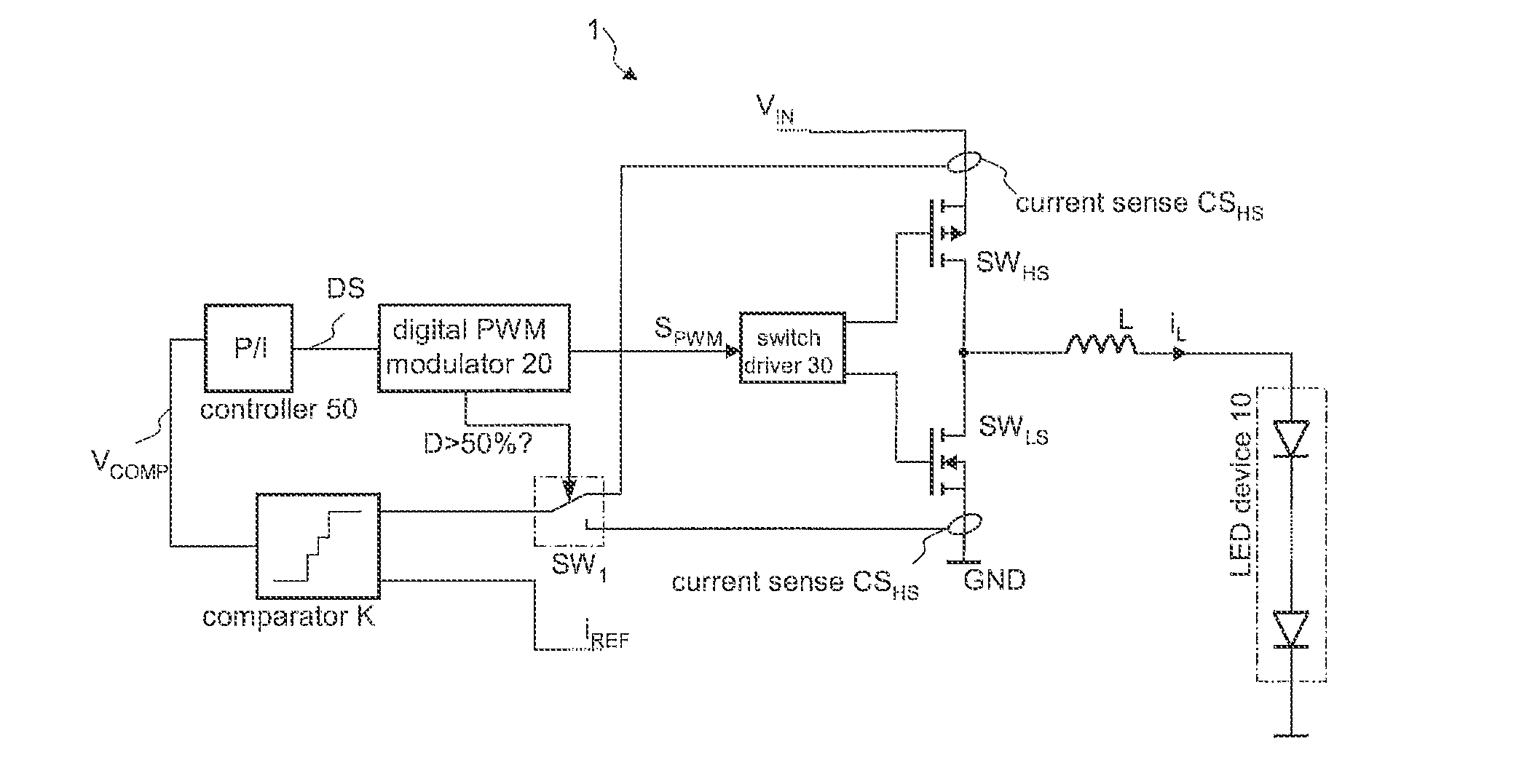
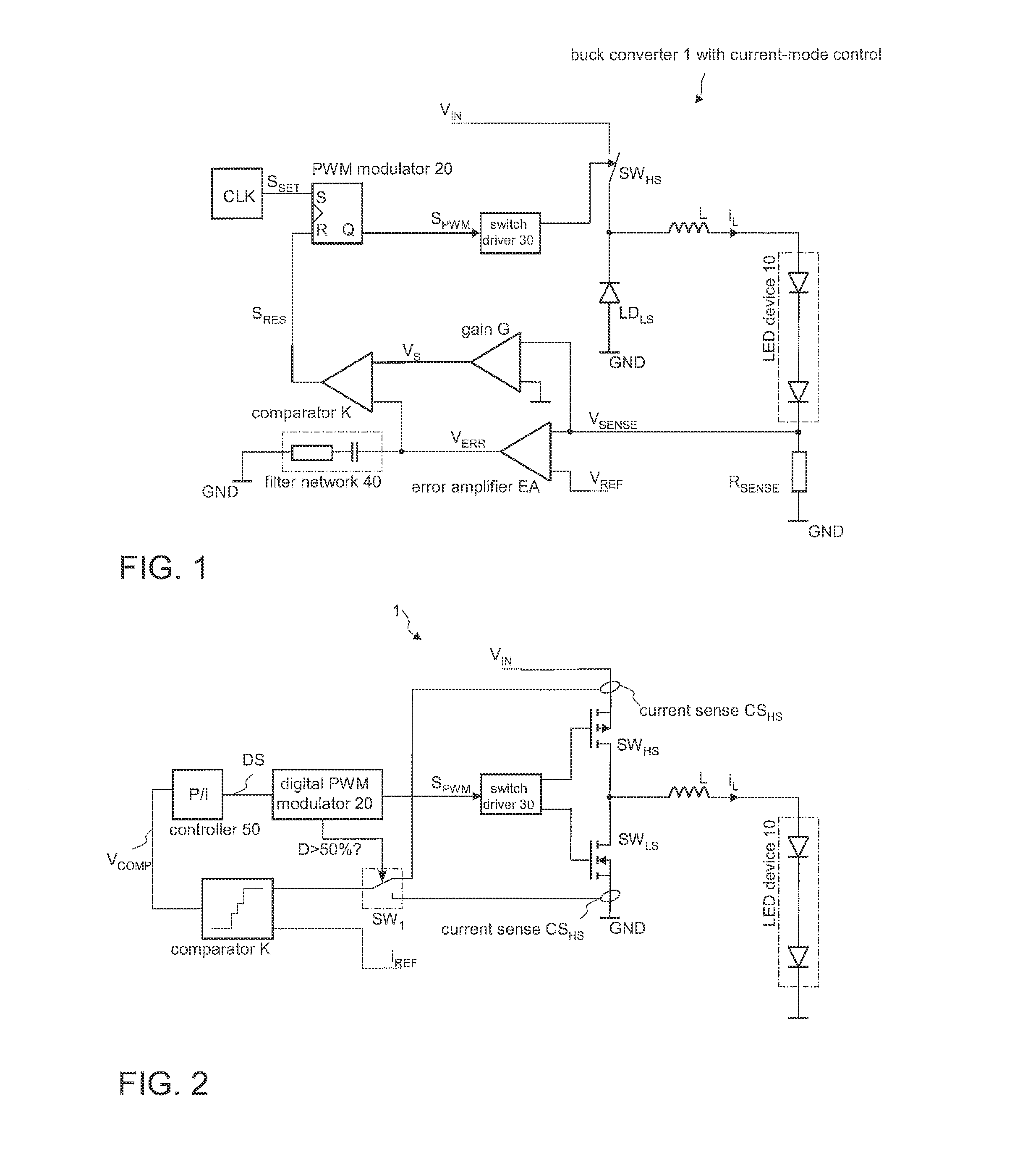
[0018]In the following the present invention is discussed using a LED driver as an example. It should be noted, however, that the switching converter control circuit can readily be employed to provide any arbitrary load (other than LEDs) with a regulated load current. In the examples discussed herein a buck converter is used. However, any other switching converter, such as a boost converters, a buck-boost converter, a boost-buck (split-pi) converter, a Ĉuk converter, a SEPIC converter, a zeta converter, etc. may be employed instead.

[0019]FIG. 1 illustrates the function and the basic structure of a buck converter and a respective control circuit for controlling the switching operation thereof thereby implementing an output current regulation. In the present example, the switching converter is a buck converter including the high side switch SWHS (e.g., a MOSFET) and a low side switch, which is a diode SWLS in the present example. Both switches are connected in series to form a half br...


PUM


Abstract

A control circuit can control the operation of a switching converter to provide a regulated load current to a load. The switching converter includes an inductor and a high-side and a low side-transistor for switching the load current provided via the inductor. A digital modulator is configured to provide a modulated signal having a duty cycle determined by a digital duty cycle value. A current sense circuit is coupled to at least one of the transistors and is configured to regularly sample a load current value. A comparator is coupled to the current sense circuit and is configured to compare the sampled load current value with a first threshold and to provide a respective comparator output signal. A regulator is configured to receive the comparator output signal and to calculate an updated digital duty cycle value.

Description

[0001]This application claims priority to European Patent Application No. 11182620, which was filed Sep. 23, 2011 and is incorporated herein by reference.TECHNICAL FIELD[0002]The present invention relates to the digital control of a switching converter, particularly to closed loop control of DC / DC converters for providing a specific desired current to illumination devices which are, e.g., based on light emitting diodes (LEDs).BACKGROUND[0003]Switching converters such as DC / DC converters usually provide a regulated output voltage. However, in some applications a regulated output current is required. This is particularly the case when the load to be supplied with electrical energy is current driven. One important type of current-driven loads are light emitting diodes (LEDs) which become increasingly important in the field of illumination devices.[0004]Modern LED-based illumination devices usually include a series circuit of several individual LEDs. Thus, the LEDs “share” a common regu...

Claims


Application Information

Patent Timeline
Patent Type & Authority Applications(United States)
IPC IPC(8): G05F1/46H05B44/00
CPCG05F1/468H05B33/0854H05B33/0815H05B45/10H05B45/39H05B45/375H05B45/3725
Inventor CAPODIVACCA, GIOVANNIMILANESI, PAOLOSCENINI, ANDREA
Owner INFINEON TECH AG
Why Eureka
Try Eureka