

Voltage monitor
- Summary
- Abstract
- Description
- Claims
- Application Information
AI Technical Summary
Benefits of technology
Problems solved by technology
Method used
Image

Examples
Embodiment Construction
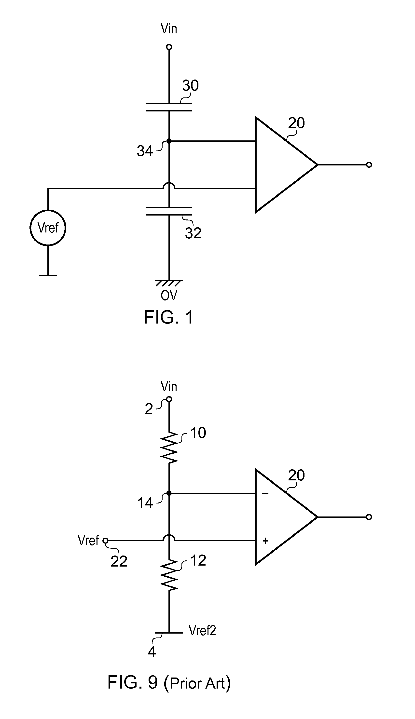
[0021]FIG. 9 is a circuit diagram of a prior art voltage monitor. In such an arrangement, first and second resistors 10 and 12 are connected in series between an input node 2 to which an input voltage Vin is supplied and a further node 4 which is held at a reference voltage, Vref2, which is typically, but not necessarily a local ground voltage, and hence can be regarded as being at zero volts. The resistors 10 and 12 have respective values R1 and R2 such that the voltage Vout occurring at an output node 14 between the resistors is given by
Vout=Vin·R2R1+R2
[0022]Typically a first input, such as an inverting input, of a comparator 20 is connected to the node 14. A voltage reference 22 is connected to a second input, typically a non-inverting input, of the comparator 20. In use, the comparator acts to compare the voltage at its first and second inputs and gives an output indicative of which one has the higher voltage.
[0023]Whilst such a circuit works well, it has several disadvantages. ...
PUM
 Abstract
Description
Claims
Application Information