Eureka AIR delivers breakthrough ideas for toughest innovation challenges, trusted by R&D personnel around the world.

System and method for latency measurement at each network element participating as an rtp relay in a telecommunication network

Active Publication Date: 2013-04-04
GOOGLE TECH HLDG LLC
View PDF5 Cites 15 Cited by
  • Summary
  • Abstract
  • Description
  • Claims
  • Application Information

AI Technical Summary

Benefits of technology

The present invention provides a system and method to measure the latency introduced at each network element that participates as an RTP relay in a telecommunication network. This allows for improved control and management of network performance. The system includes a receiver, a latency generator, and a transmitter, which work together to create a real-time transport packet. The output packet is based on the received packet and is transmitted to the destination terminal. The main technical effect is the ability to accurately measure and manage latency in real-time transport networks, which can improve network performance and reduce delays in data transmission.

Problems solved by technology

With an increasing number of users utilizing the networks for voice, data and video services, the network operators are facing the next big issue in ensuring the quality of service to the end users.
In regards to the voice quality, the major problem that comes up is the voice transmission delay introduced by the network itself.
In situations when one or more SBCs or switches are taken off of the network, resulting in traffic that is overloaded on backup SBCs and switches, end-to-end network delay is higher due to longer latency.

Method used


Image

  • System and method for latency measurement at each network element participating as an rtp relay in a telecommunication network
  • System and method for latency measurement at each network element participating as an rtp relay in a telecommunication network
  • System and method for latency measurement at each network element participating as an rtp relay in a telecommunication network

Examples


Embodiment Construction

[0046]Systems and methods, in accordance with embodiments of the present invention, provide a solution to measure the latency introduced in a telecommunication network by participating network elements that act as an RTP relay in the telecommunication network. The measured latency information can be used by a network administrator to cause an alarm for running diagnostics on the network element responsible for the highest latency value, which exceeds the threshold for a minimum tolerable latency value.

[0047]FIG. 3 illustrates a system 300 for transfer of an RTP packet in accordance with an embodiment of the invention.

[0048]As illustrated in FIG. 3, system 300 includes a source terminal 302, a receiver 304, a latency generator 306, a transmitter 308 and a destination terminal 310. Receiver 304, latency generator 306, and transmitter 308 are illustrated as individual devices; however, in some embodiments at least two of receiver 304, latency generator 306, and transmitter 308 may be c...


PUM


Abstract

A real-time transport packet creating system and method are provided for use with a source terminal, a destination terminal and a real-time transport packet. The real-time transport packet creating device includes a receiver, a latency generator and a transmitter. The receiver can receive the real-time transport packet from the source terminal at a first time. The latency generator can generate an output real-time transport packet. The transmitter can transmit the output real-time transport packet to the destination terminal at a second time. The output real-time transport packet is based on the received real-time transport packet, the first time and the second time.

Description

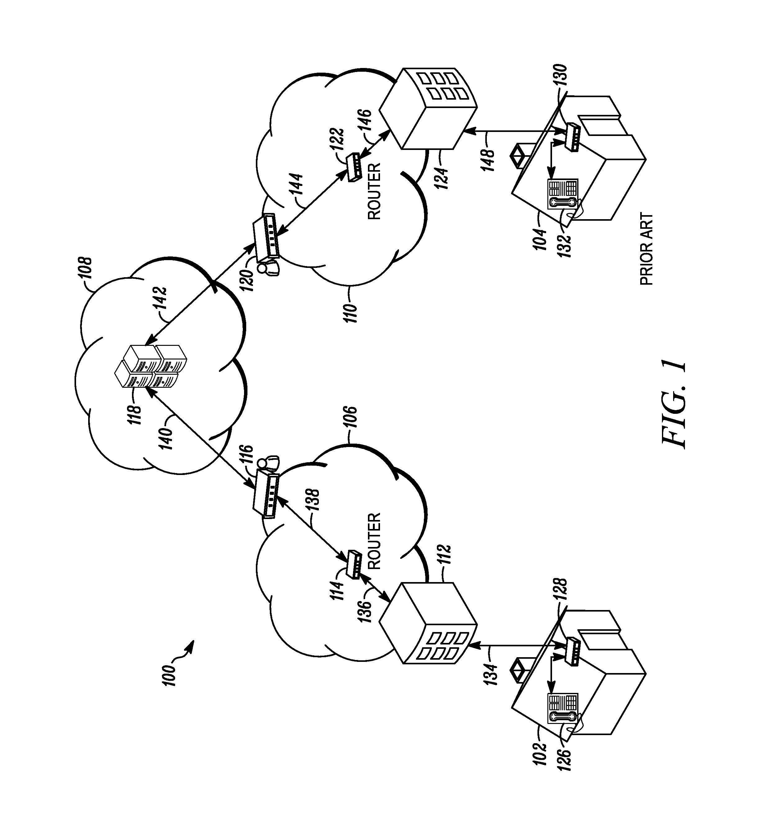
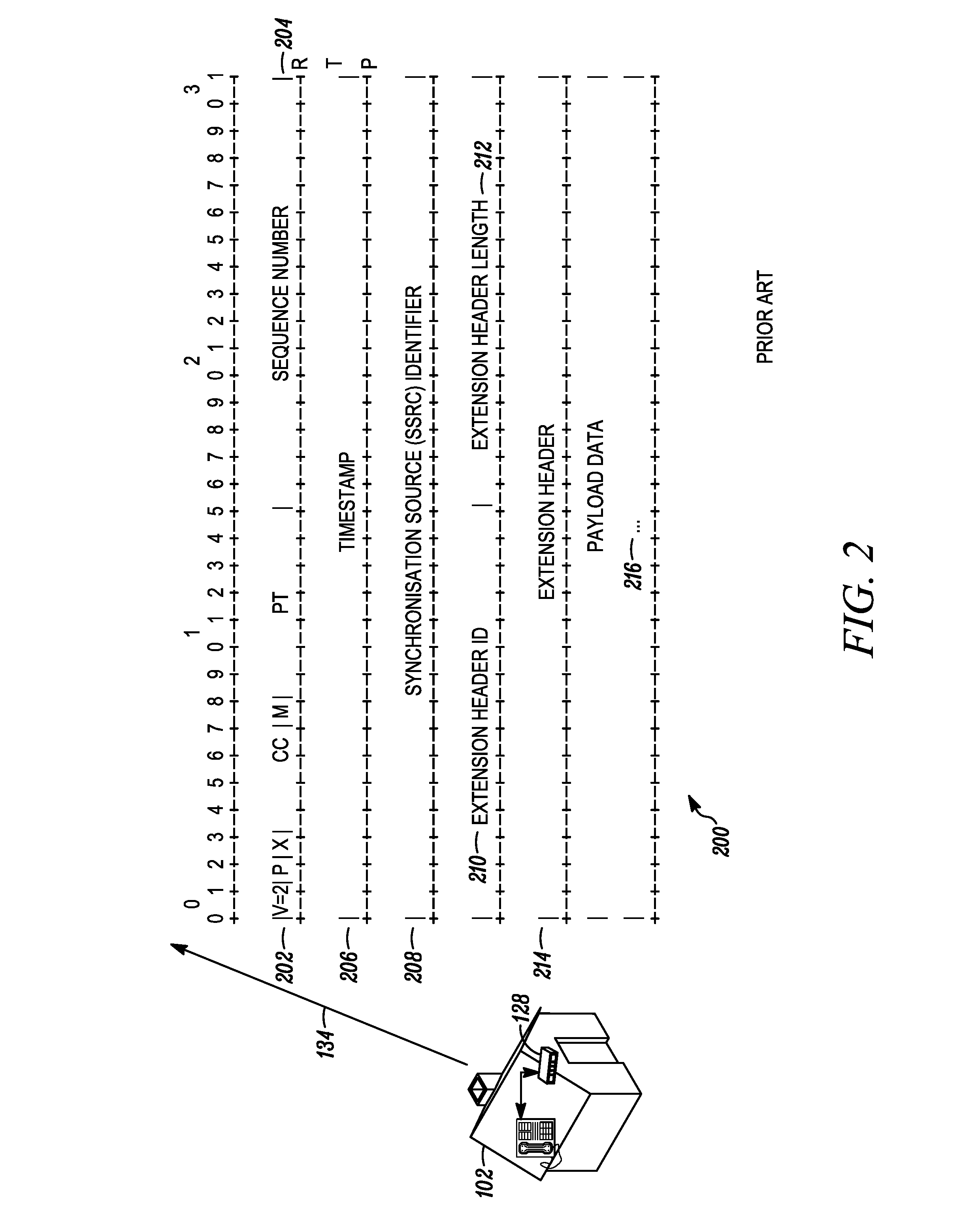
BACKGROUND[0001]The present invention relates to the field of telecommunication networks, in particular, data latency introduced in fiber optics communication networks.[0002]In a telecommunication network, messages generated by a source terminal pass through a network of links and nodes until they arrive at a destination terminal. A telecommunication network using fiber optics communications is able to provide voice, video and data services straight to the customers' homes or businesses.[0003]Voice over Internet Protocol (Voice over IP, VoIP) is one of a family of internet technologies for delivery of voice communications and multimedia sessions over Internet Protocol (IP) networks, such as the internet. Real-time Transport Protocol (RTP) in conjunction with RTP Control Protocol (RTCP) is commonly used for delivering audio and video over IP networks. Voice telephony services, such as services normally associated with POTS (Plain Old Telephone Service), provided to the customers inte...

Claims


Application Information

Patent Timeline
IPC IPC(8): H04L12/00
CPCH04L65/605H04L65/80H04L65/608H04L65/765H04L65/65
Inventor SRIDHAR, SRIRAM
Owner GOOGLE TECH HLDG LLC
Why Eureka
Eureka Blog
Learn More