
Hardware-Based Weight And Range Limitation System, Apparatus And Method

a weight and range limitation and hardware technology, applied in the field of hardware-based weight and range limitation systems, can solve the problems of inability to address the various objectives, failure to address the implementation of range and load limitations in the 3d flight extent, and inability to meet the various objectives

Inactive Publication Date: 2013-04-04
PNC BANK NAT ASSOC
View PDF4 Cites 66 Cited by
  • Summary
  • Abstract
  • Description
  • Claims
  • Application Information

AI Technical Summary

Benefits of technology

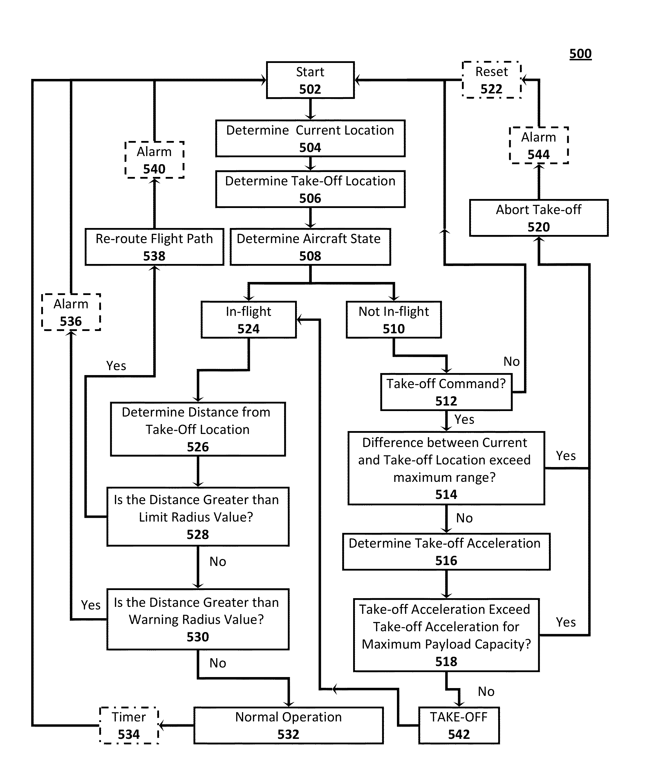
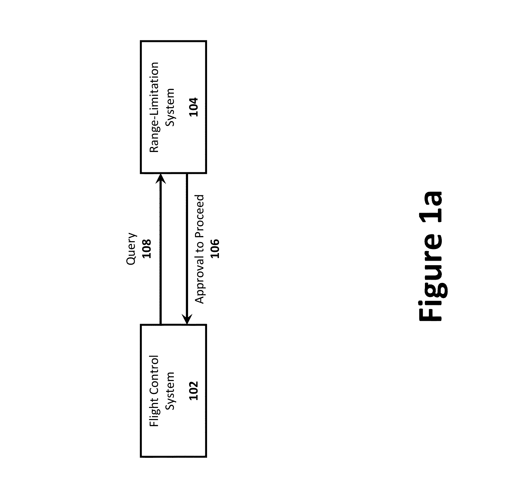
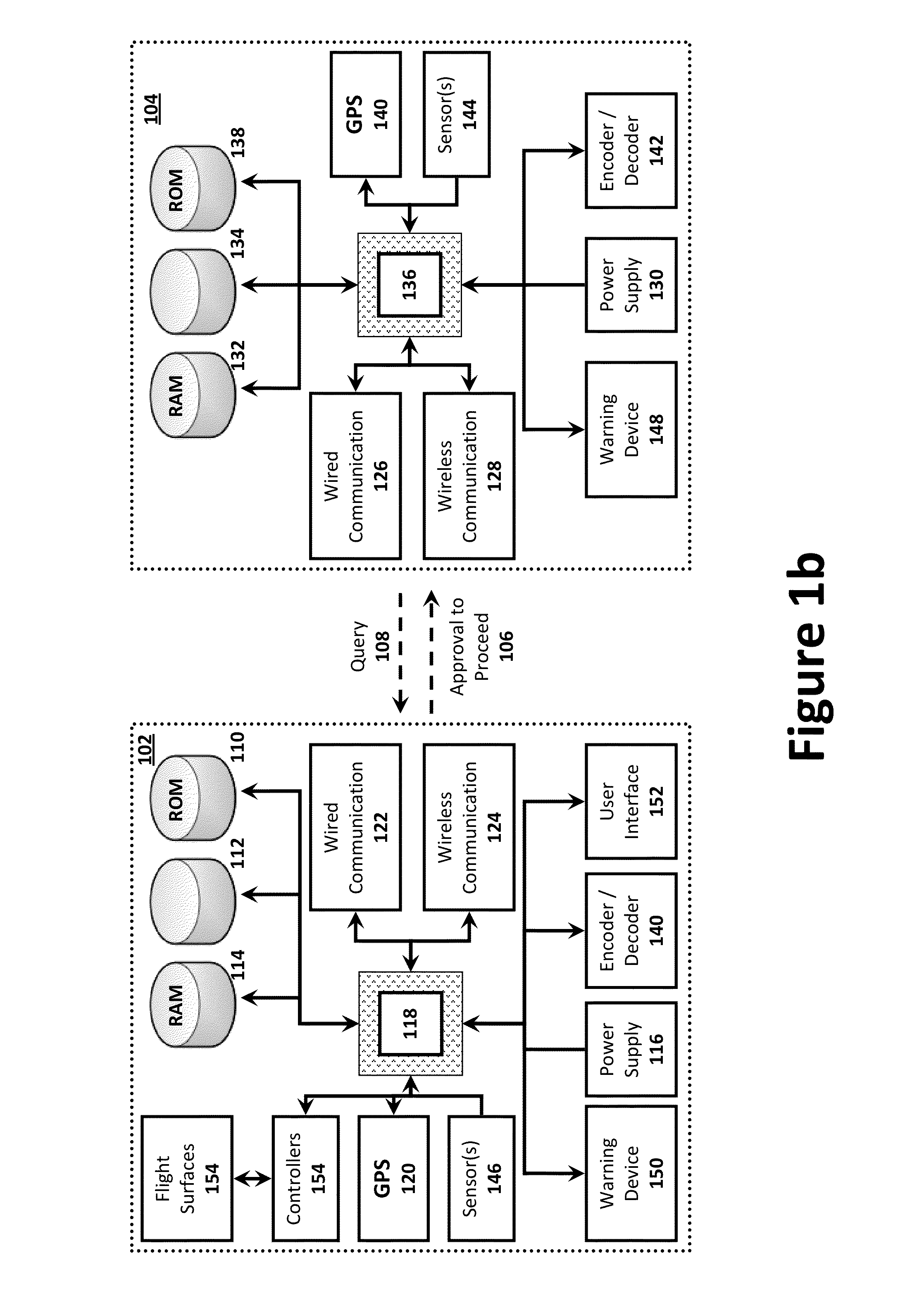
The present invention provides a non-software-based solution for restricting a system's range and payload using an ASIC and flight control system. The invention includes a GPS receiver, storage device, inclinometer, sensor for air speed, range calculation circuit, weight limitation circuit, and a device to communicate an approval-to-proceed signal. The weight limitation circuit dynamically calculates the vehicle's payload and compares it to a predetermined threshold value to determine if the vehicle can safely take off. The range calculation circuit calculates the vehicle's location and compares it to a stored location to determine if the vehicle can safely land within the range. The invention can provide a safer and more reliable system for restricting vehicle range and payload.

Problems solved by technology

Unfortunately, they fail to address the various objectives of the present invention.
As with Abrahamson, 3D Flight Extents fails to address implementation of range and load limitations for increasing MTCR Category II compliance.
However, both of these solutions are unacceptable.
A software-based system would not be acceptable under the MTCR guidelines, and airframe modifications would not be an option for an OPA capable of maintaining full operational performance in the manned mode as well as the unmanned mode.

Method used


Image

  • Hardware-Based Weight And Range Limitation System, Apparatus And Method
  • Hardware-Based Weight And Range Limitation System, Apparatus And Method
  • Hardware-Based Weight And Range Limitation System, Apparatus And Method

Examples


Embodiment Construction

[0022]The present disclosure endeavors to provide a non-software-based solution for restricting a system's range and / or the payload using, for example, a Application-Specific Integrated Circuit (ASIC) installed in the flight control system. Preferred embodiments of the present invention will be described hereinbelow with reference to the accompanying drawings. In the following description, well-known functions or constructions are not described in detail, since they would obscure the invention in unnecessary detail. For this application, the following terms and definitions shall apply:

[0023]The terms “communicate” and “communicating,” as used herein, refer to both transmitting, or otherwise conveying, data from a source to a destination and delivering data to a communications medium, system, channel, network, device, wire, cable, fiber, circuit, and / or link to be conveyed to a destination.

[0024]The term “computer,” as used herein, refers to a programmable device designed to sequenti...


PUM


Abstract

The present disclosure endeavors to provide systems, methods and apparatus for ensuring aircraft compliance with governmental guidelines, such as, for example, MRCR Category II compliance. A hardware-based system may be employed to reduce range and / or payload below predetermined ranges and a payload capacities. Also provided herein are hardware-based systems, methods, and apparatus for restricting a system's range to predetermined range and / or the payload to a predetermined limit using, for example, a Application-Specific Integrated Circuit (ASIC) installed in the flight control system.

Description

TECHNICAL FIELD[0001]The present invention relates to Systems and Methods for Range and / or Payload Limitation System (RPLS). More specifically, the present invention relates to Systems and Methods for RPLS for Missile Technology Control Regime (MTCR) Category II Optionally Piloted Aircraft (OPA) and Unmanned Aerial Vehicles (UAV) and Systems and Methods for Complying with Aircraft Export Security Controls.BACKGROUND INFORMATION[0002]Export of an OPA or UAV requires approval by the U.S. Department of State and the system has to meet MTCR guidelines. The guidelines are established by international treaty and governed by representatives from the signatory countries. Generally speaking, MTCR Category I items have a strong presumption for denial of export. MTCR Category I items include, for example, all OPAs and UAVs that have a range over 300 km and a payload capacity over 500 kg. However, items below that range and / or payload are typically considered MTCR Category II items and are like...

Claims


Application Information

Patent Timeline
Patent Type & Authority Applications(United States)
IPC IPC(8): G06F17/00
CPCB64C13/18B64C2201/145B64D45/00G08G5/006G08G5/0021G08G5/0039G05D1/0055B64U2201/104
Inventor WASHINGTON, TOMHISAM, THORSTENGOMEZ, MARTIN
Owner PNC BANK NAT ASSOC
Learn More