Method and device for reducing the temperature tolerance of sheathed-element glow plugs

a technology of sheathed-element glow plugs and temperature tolerance, which is applied in the direction of mechanical equipment, machines/engines, lighting and heating apparatus, etc., can solve the problems of reducing the service life affecting the combustion behavior of individual sheathed-element glow plugs, and recognizing defective glow plugs. , to achieve the effect of reducing the temperature tolerance of sheathed-element glow plug

Inactive Publication Date: 2013-04-11
ROBERT BOSCH GMBH
View PDF14 Cites 8 Cited by
  • Summary
  • Abstract
  • Description
  • Claims
  • Application Information

AI Technical Summary

Benefits of technology

The present invention relates to a method for reducing the temperature tolerance of sheathed-element glow plugs in internal combustion engines. By doing so, the behavior of the engine during a cold start is improved, hydrocarbon and carbon monoxide emissions are reduced, and the service life of the glow plugs is increased. The method can be performed without additional devices or techniques and allows for the classification of the glow plugs based on simple features like power, resistance, and temperature tolerance. Additionally, the method ensures that the desired glow temperature is maintained while increasing or lengthening the service life of the glow plugs.

Problems solved by technology

This is generally approximately + / −50° C. The temperature differences of the individual sheathed-element glow plugs, which result from the temperature tolerance during manufacturing, cause a negative influence of the combustion behavior during a cold start and the emission operation, however.
In addition, the service life of individual sheathed-element glow plugs is reduced due to temperature deviations.
In addition, if values exceed or fall below diagnostic limiting values, the glow plug may be recognized as defective, no voltage adaptation being performed in this case.

Method used


Image

  • Method and device for reducing the temperature tolerance of sheathed-element glow plugs
  • Method and device for reducing the temperature tolerance of sheathed-element glow plugs
  • Method and device for reducing the temperature tolerance of sheathed-element glow plugs

Examples


Embodiment Construction

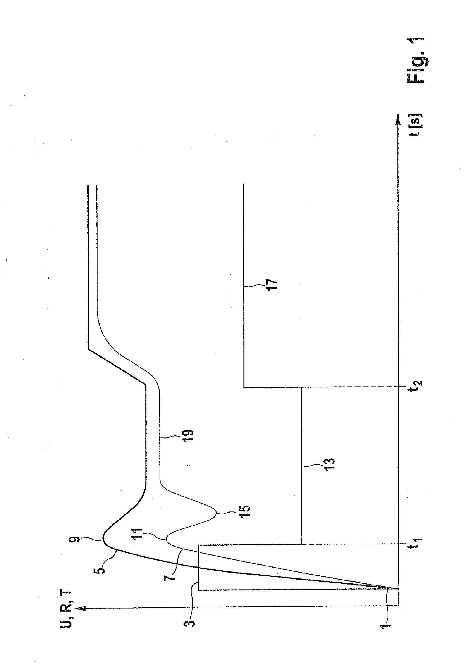
[0028]The curves of temperature, resistance, and voltage as a function of time are shown in the single FIGURE.

[0029]To classify sheathed-element glow plugs which are outside a predefined temperature tolerance, features which describe the dynamic behavior and the stationary behavior of the sheathed-element glow plug are initially calculated. For this purpose, it is possible, for example, to activate the sheathed-element glow plug using a predefined control voltage in an internal combustion engine of a motor vehicle when the motor vehicle is stationary and therefore the surrounding air is calm, in order to determine the features of the sheathed-element glow plug. Over the entire period of time of the classification and the registration of the temperature tolerance of the sheathed-element glow plug, voltage and current are measured and characteristic values are calculated at predefined timestamps. The calculated characteristic values are, for example, the resistance of the sheathed-ele...


PUM


Abstract

A method for reducing the temperature tolerance of sheathed-element glow plugs is described, in which, in a first step, the sheathed-element glow plugs of an auto-ignition internal combustion engine are classified into at least two temperature classes, at least one temperature class including a temperature range above a setpoint temperature range, at least one temperature class including a temperature range below the setpoint temperature range, and / or one temperature class including the setpoint temperature range. In a second step, the control voltage of sheathed-element glow plugs which were assigned to a temperature class which includes a temperature range above the setpoint temperature range is reduced, and the control voltage of sheathed-element glow plugs which were assigned to a temperature class which includes a temperature range below the setpoint temperature range is increased. A device for performing the method is also described.

Description

FIELD OF THE INVENTION[0001]The present invention relates to a method for reducing the temperature tolerance of sheathed-element glow plugs. Furthermore, the present invention relates to a device for reducing the temperature tolerance of sheathed-element glow plugs.BACKGROUND INFORMATION[0002]At low temperatures, auto-ignition internal combustion engines require an ignition aid. In particular, the ignition aid is required for starting the internal combustion engine. Sheathed-element glow plugs are used for this purpose, which are each installed in the cylinder head and protrude into the combustion chamber. The sheathed-element glow plugs typically include a glow plug, which provides a hot point to the fuel-air mixture to be ignited, on which the fuel-air mixture may ignite.[0003]In typically used sheathed-element glow plugs, the glow plug includes a heating element designed as an electrical resistor. A voltage is applied to the heating element, so that a current, which heats the glo...

Claims


Application Information

Patent Timeline
Patent Type & Authority Applications(United States)
IPC IPC(8): F02P19/02
CPCF02P19/02F02P19/023F02P19/021F02P19/027F02P19/025F23Q7/00
Inventor JOOS, SASCHA
Owner ROBERT BOSCH GMBH
Why Eureka
Try Eureka