Electronic disc brake

a technology of electronic disc brake and braking disc, which is applied in the direction of braking system, braking, gearing, etc., can solve the problems that the b>1/b> may be disadvantageous in terms of operating noise during braking, and achieve the effect of reducing operating noise, reducing volume and efficient operation

Inactive Publication Date: 2013-04-11
HL MANDO CORP
View PDF7 Cites 33 Cited by
  • Summary
  • Abstract
  • Description
  • Claims
  • Application Information

AI Technical Summary

Benefits of technology

[0022]Therefore, it is an aspect of the present invention to provide an electronic disc brake which has a reduced volume, reduces operating noise, and is efficiently operated by improving structures of respective parts including a motor generating driving force, gears transmitting the driving force and a reducer reducing rotating force, and a connection structure between the parts.

Problems solved by technology

Further, the electronic disc brake 1 may be disadvantageous in terms of operating noise during braking by means of the gears configured in a multiple stage structure.

Method used


Image

  • Electronic disc brake
  • Electronic disc brake
  • Electronic disc brake

Examples


Embodiment Construction

[0039]Reference will now be made in detail to the embodiments of the present invention, examples of which are illustrated in the accompanying drawings, wherein like reference numerals refer to like elements throughout. The terms used in the following description are terms defined taking into consideration the functions obtained in accordance with the embodiments, and the definitions of these terms should be determined based on the overall content of this specification. Therefore, the configurations disclosed in the embodiments and the drawings of the present invention are only exemplary and do not include all of the technical spirit of the invention, and thus it will be appreciated that the embodiments may be variously modified and changed.

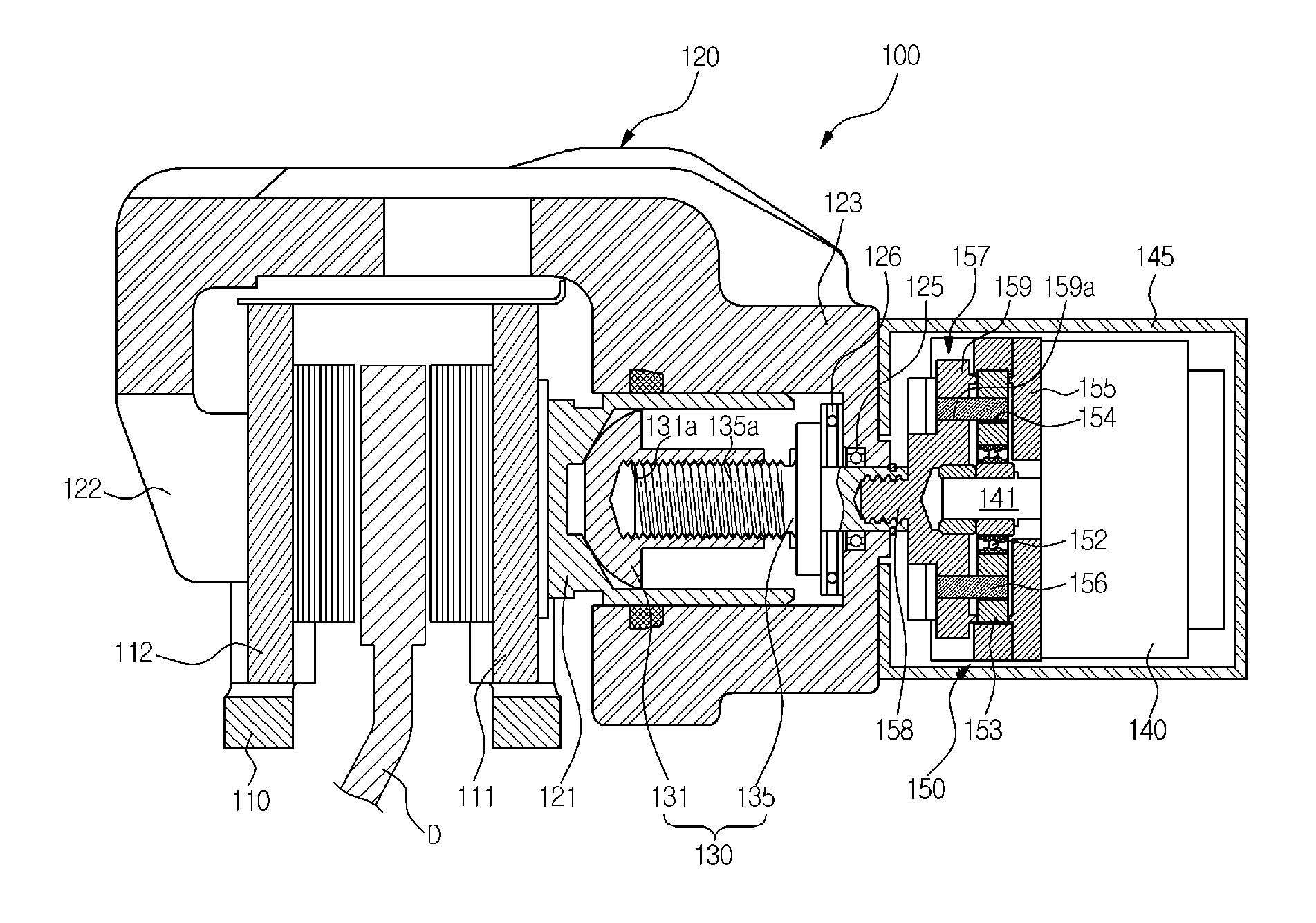
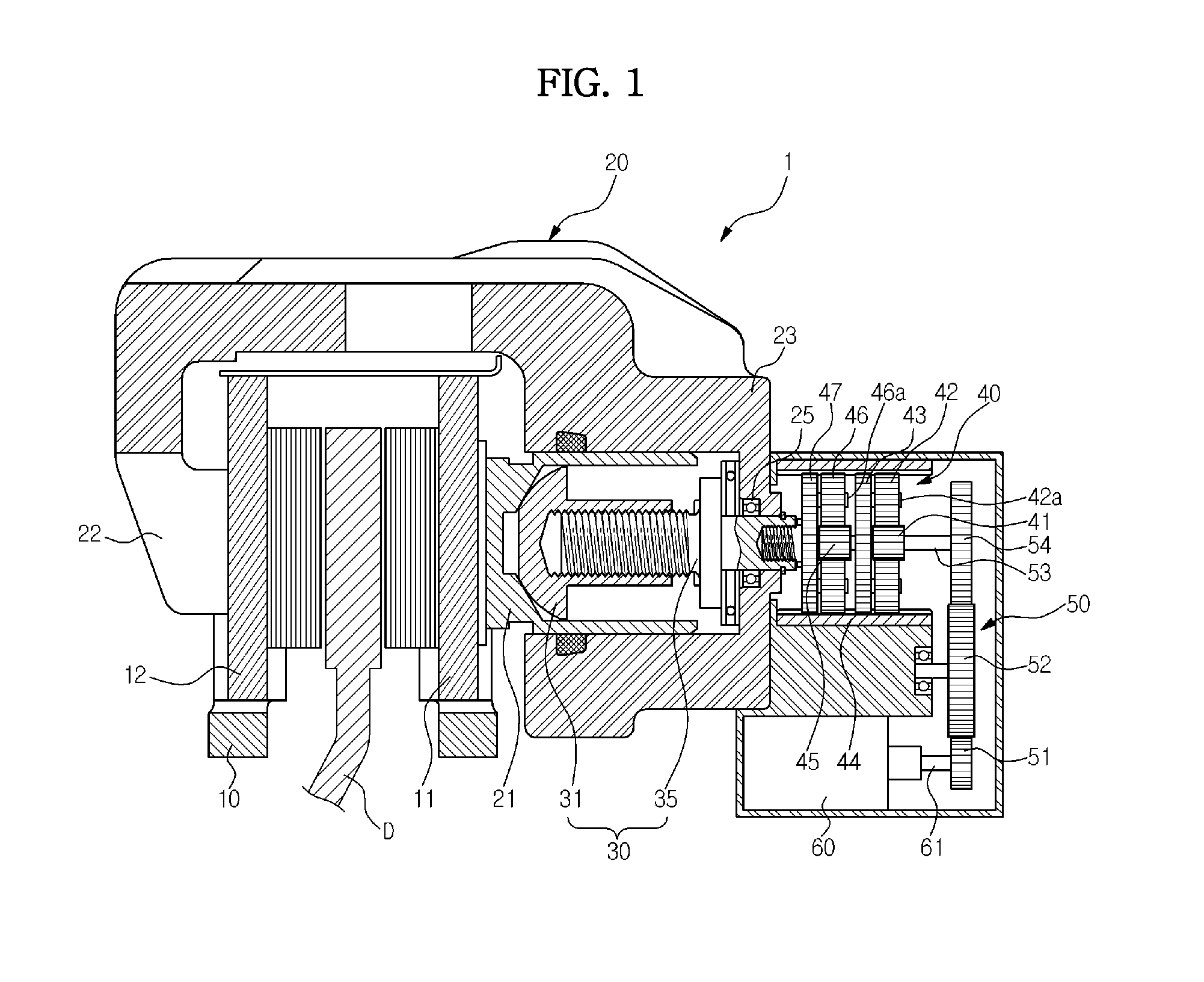
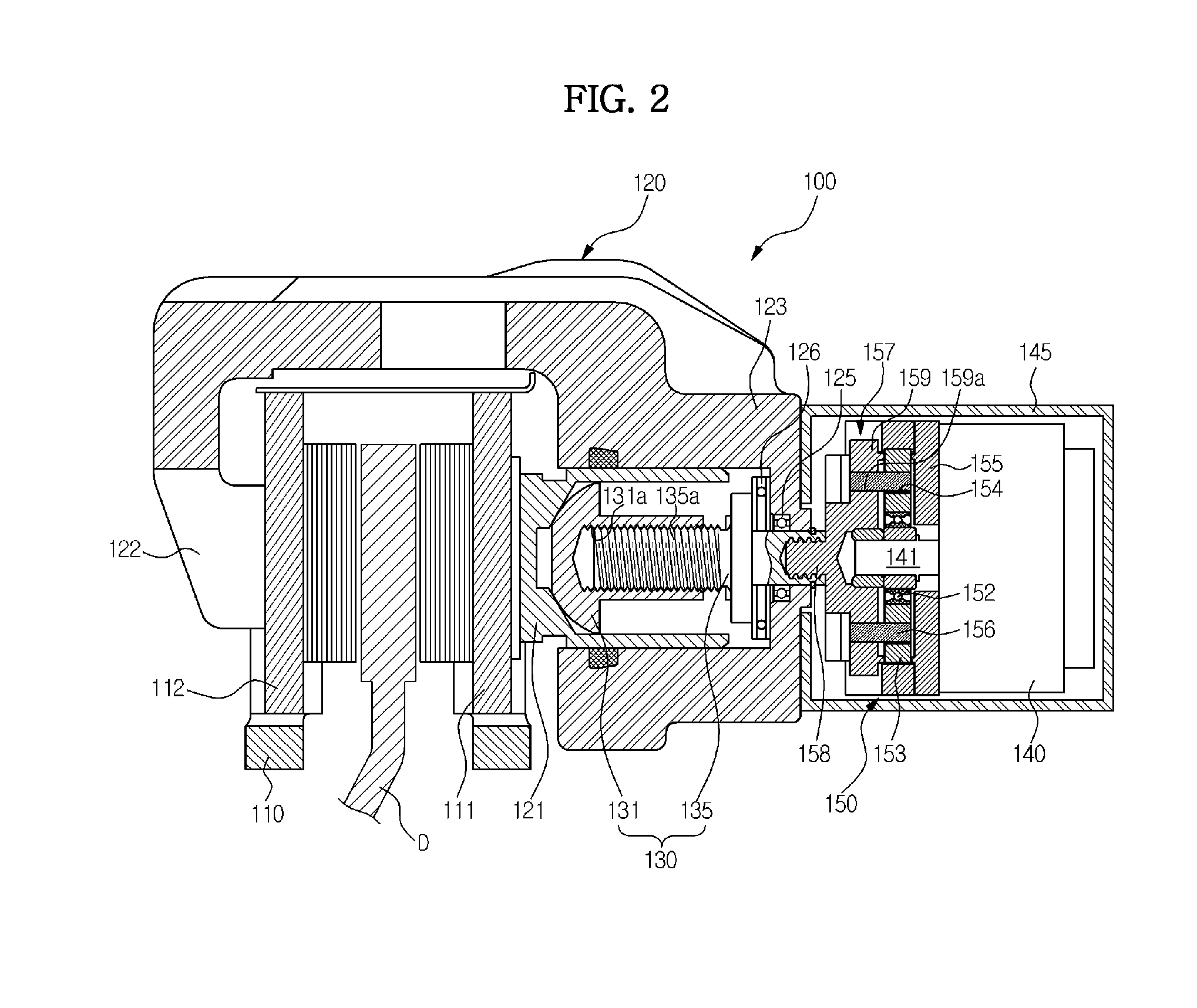
[0040]FIG. 2 is a cross-sectional view illustrating an electronic disc brake in accordance with one embodiment of the present invention.

[0041]With reference to FIG. 2, the electronic disc brake 100 includes a disc D rotating together with a wheel ...


PUM


Abstract

Disclosed herein is an electronic disc brake in which driving force of a motor may be transmitted to a gear unit in a serial manner. The electronic disc brake which has a carrier, a caliper housing, a pair of pad plates disposed at both sides of a disc, and a piston installed within a cylinder part and pressing one of the pair of pad plates toward the disc, includes a spindle member passing through the rear wall of the caliper housing and rotated within the cylinder part, a nut member screw-connected to the spindle member and pressing the piston or releasing pressing of the piston, a motor generating driving force, and a cycloid reducer amplifying the driving force generated from the motor and transmitting the amplified driving force to the spindle member, and the motor, the cycloid reducer and the spindle member are coaxially connected in series.

Description

CROSS-REFERENCE TO RELATED APPLICATION[0001]This application claims the benefit of Korean Patent Application No. 2011-0102791, filed on Oct. 10, 2011 in the Korean Intellectual Property Office, the disclosure of which is incorporated herein by reference.BACKGROUND[0002]1. Field[0003]Embodiments of the present invention relate to an electronic disc brake having a parking function in which driving force of a motor may be transmitted to a gear unit in a serial manner.[0004]2. Description of the Related Art[0005]In general, a parking brake device stops a vehicle if it is desired to park the vehicle, and serves to hold a wheel of the vehicle so as not to rotate.[0006]Recently, an electronic parking brake (EPB) system, driving of which is electronically controlled, is used, and such an EPB system is mounted on a conventional disc brake and performs the function of the parking brake. Here, EPB systems are divided into a cable puller type, a motor-on-caliper type and a hydraulic parking bra...

Claims


Application Information

Patent Timeline
Patent Type & Authority Applications(United States)
IPC IPC(8): B60T1/06
CPCB60T13/741F16D65/18F16D2125/50F16D2125/40F16D2125/48F16D2121/24F16D65/092F16D65/14F16H1/34
Inventor YU, SUNG WOOKKO, CHANG BOKLEE, YOUNG SONG
Owner HL MANDO CORP
Why Eureka
Try Eureka