

Apparatus for generating power from a turbine engine
a technology of turbine engine and apparatus, which is applied in the direction of engine starter, electric generator control, machine/engine, etc., can solve the problems of adding additional weight and volume to the engin
- Summary
- Abstract
- Description
- Claims
- Application Information
AI Technical Summary
Benefits of technology
Problems solved by technology
Method used
Image

Examples
first embodiment
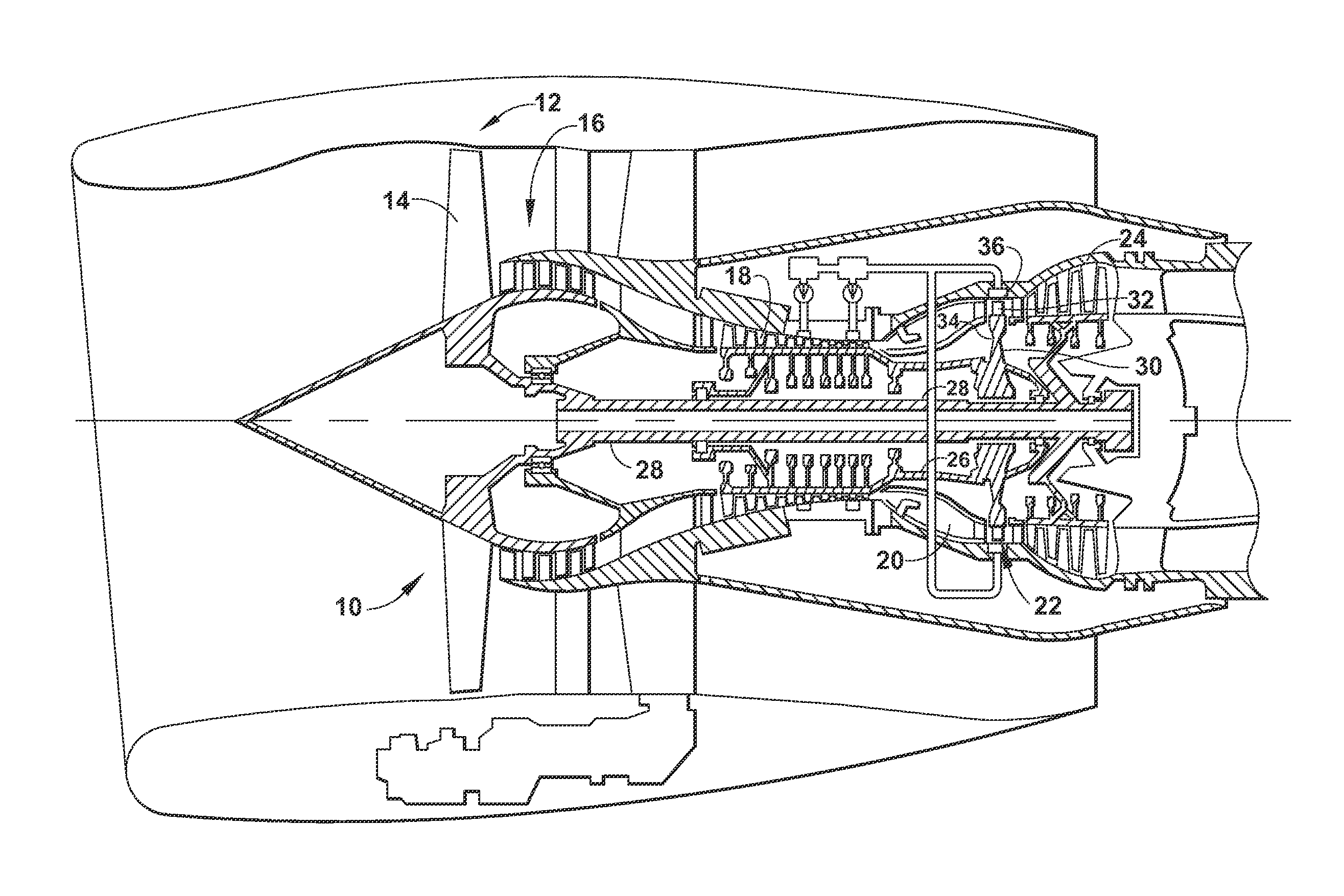
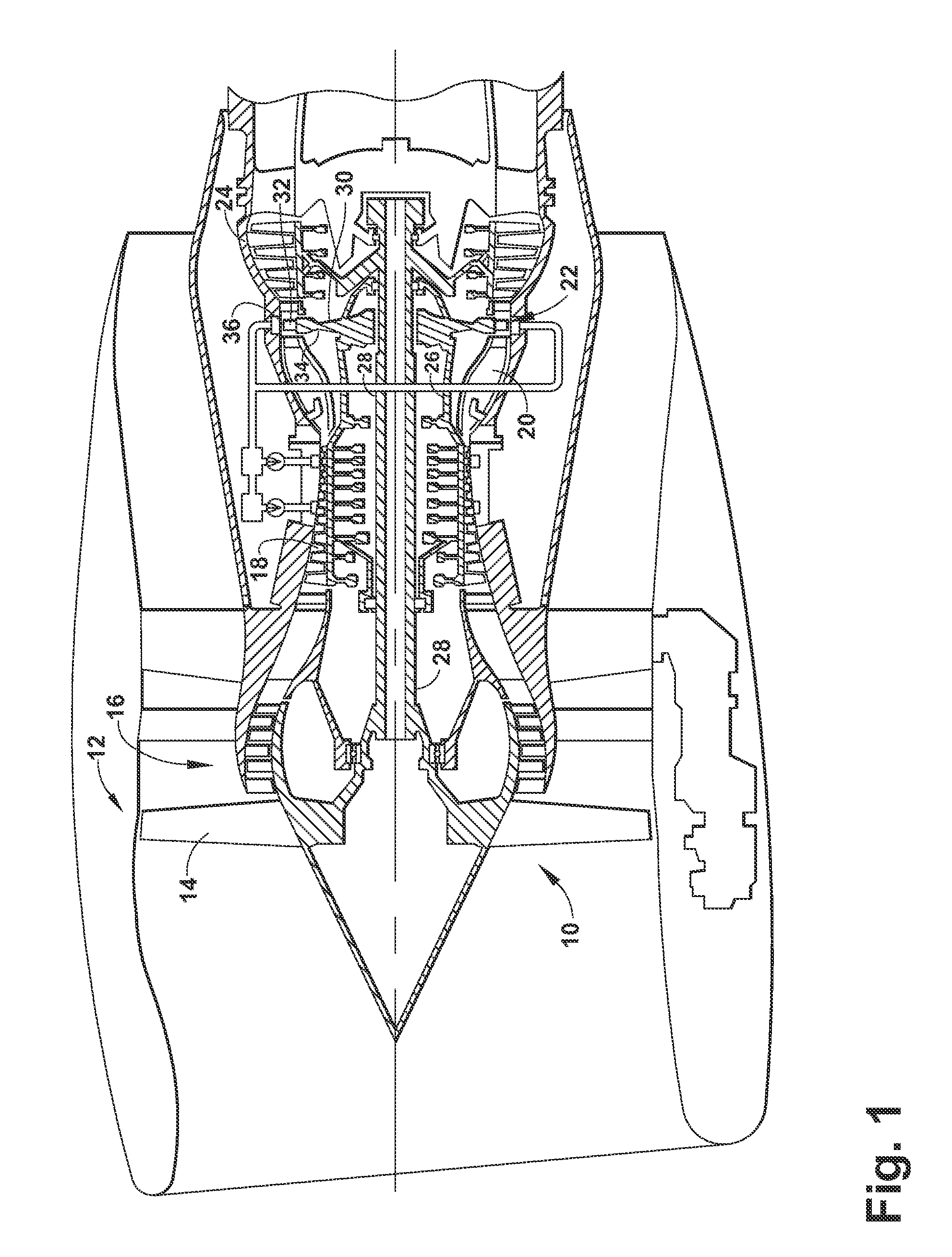
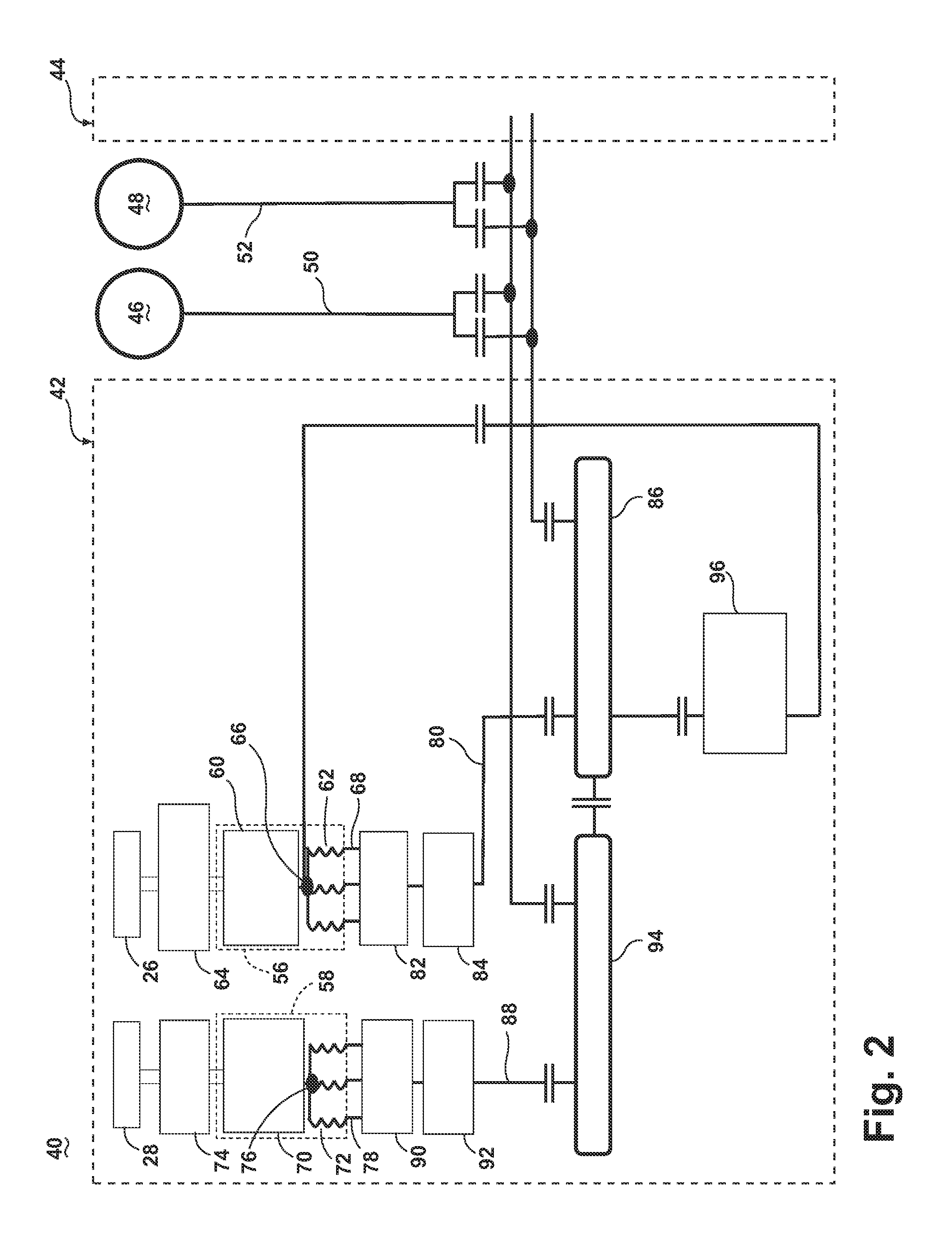
[0021]FIG. 2 is a schematic block diagram of an electrical power system architecture 40 according to the invention. The system architecture 40 includes multiple engine systems, shown herein as including at least a left engine system 42 and a right engine system 44. The left and right engine systems 42, 44 may be substantially identical; therefore, only the left engine system 42 will be described in detail for the sake of brevity. The left engine system 42 can include the HP and LP spools 26, 28 of the gas turbine engine 10 shown in FIG. 1, although the system architecture 40 has application to other engines as well. The left engine system 42 shown herein uses mechanical power provided by two spools, the HP spool 26 and the LP spool 28. However, the system architecture 40 could also be implemented on an engine having more than two spools, such as a 3-spool engine having an intermediate pressure spool in addition to the HP and LP spools. The system architecture 40 can further include ...
second embodiment
[0052]FIG. 6 is a schematic block diagram of an electrical power system architecture 140 according to the invention. The system architecture 140 may be substantially similar to the system architecture 40 shown in FIG. 2; therefore, like elements will be referred to using the same reference numerals. One difference between the system architecture 140 shown in FIG. 6 and the system architecture 40 shown in FIG. 2 is that, for both ATU integrated generators 56, 58, the ATU section 62, 72 functions to transform the three phase outputs of the power supply 66, 76 into a nine phase power output 142, 144 by adding two secondary windings instead of adding three windings.
[0053]FIG. 7 is an electrical diagram of the ATU integrated starter-generator 56 and the first AC-to-DC power converter for use in the electrical power system architecture 140 of FIG. 6. The first and second ATU integrated generators 56, 58 and AC-to-DC power converters may be substantially identical for both the HP spool 26 ...
third embodiment
[0066]FIG. 10 is a schematic block diagram of an electrical power system architecture 160 according to the invention. The system architecture 160 may be substantially similar to the system architecture 40 shown in FIG. 2; therefore, like elements will be referred to using the same reference numerals. One difference between the system architecture 160 shown in FIG. 10 and the system architecture 40 shown in FIG. 2 is that the ATU section 62 includes an AC power output 162 that is supplied to an AC bus 164, in addition to the nine phase power output 68.
[0067]FIG. 11 is an electrical diagram of the ATU integrated starter-generator 56 and the first AC-to-DC power converter for use in the electrical power system architecture 160 of FIG. 10. The ATU integrated starter-generator 56 can be substantially similar to the ATU integrated starter-generator 56 of the first embodiment shown in FIG. 3, with the exception that additional secondary windings 166a to 166c are provided on the main windin...
PUM
 Abstract
Description
Claims
Application Information